ahmad_abdulghany
Advanced Member level 4
- Joined
- Apr 12, 2005
- Messages
- 1,206
- Helped
- 102
- Reputation
- 206
- Reaction score
- 22
- Trophy points
- 1,318
- Location
- San Jose, California, USA
- Activity points
- 11,769
Settling time can be simply defined as the time that PLL needs to lock after a jump or change in its inputs (may be not very accurate).
Anyway, a strange phenomena occures in PLL, I saw in second and third order PLL, that's , in case of small frequency step, there's almost no slipping in the close loop dynamic responce, wherease in realively large step, there's sometimes one cycle-slipping.
As in the attached figure,
- the blue VCO control line output from loop filter, corresponds to Δf=2MHz step in the PLL input,
- and the red the Vc signal, corresponds to Δf=10MHz step in the PLL input.
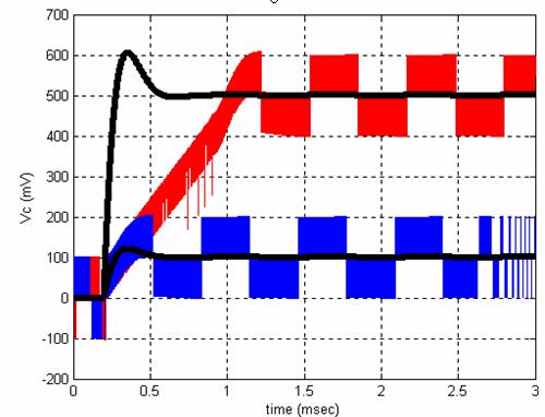
Can someone discuss some reasons for that as well as methods to compansate?
Thanks and Regards,
Ahmad,
Anyway, a strange phenomena occures in PLL, I saw in second and third order PLL, that's , in case of small frequency step, there's almost no slipping in the close loop dynamic responce, wherease in realively large step, there's sometimes one cycle-slipping.
As in the attached figure,
- the blue VCO control line output from loop filter, corresponds to Δf=2MHz step in the PLL input,
- and the red the Vc signal, corresponds to Δf=10MHz step in the PLL input.
Can someone discuss some reasons for that as well as methods to compansate?
Thanks and Regards,
Ahmad,