Continue to Site

Welcome to EDAboard.com

Welcome to our site! EDAboard.com is an international Electronics Discussion Forum focused on EDA software, circuits, schematics, books, theory, papers, asic, pld, 8051, DSP, Network, RF, Analog Design, PCB, Service Manuals... and a whole lot more! To participate you need to register. Registration is free. Click here to register now.

Reverse recovery losses in Synchronous Buck.

cupoftea

Advanced Member level 5
Joined
Jun 13, 2021
Messages
2,611
Helped
54
Reputation
108
Reaction score
115
Trophy points
63
Activity points
13,687
Hi,
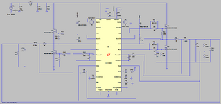
We do Synch Buck of 24vin, 13v5 out 15A out, 450kHz.
We use 60V SON5x6mm FETs.

60V FET, trr=35ns (50A, di/dt = 100A/us)

They have reverse recovery of some 40ns.

Because the datasheets dont show the dynamics of the FET reverse recovery, it is impossible for us to calculate what power will be dissipated overall, due to the reverse recovery.
Also, simulators "dont do reverse recovery", (at least not accurately) and so no estimate can be gotten from that.
May you give an estimate?
 

Attachments

  • SYNCH BUCK REV REC.png
    SYNCH BUCK REV REC.png
    62.2 KB · Views: 24
  • SYNCH BUCK REV REC.zip
    2.5 KB · Views: 26
Last edited:
actually the rev recovery current is the charge divided by the time taken to sweep out the charge - for high dV/dt, causing high -dIf/dt the peak and average current - for the time that it flows in the device - the Irev can be any value from 1A to 10A to higher . . .
 
Last edited:
Thanks, the ti.com calculator does the power dissipated in the top fet of the synch buck as as Qrr.Vin.f
where f = switching freq
But i dont believe thats an accurate appraisal of it.
Not least that our Vin isnt the same as the Vds they give for their Qrr measurement in the datasheet of the FET
 
True body diode reverse recovery should only be about the
current during the below-ground interval. This imparts the
diode forward charge that has to be taken out by the high
side (-if-- the remaining low-side-switch on time (Vdb=0)
has not been enough to do so).

You ought to be able to bench-measure body diode recovery
time in the classical manner, against on-current and temp,
change the "-1V" bias to 0.0 and see what the 'scope tells.

I'd be inclined to worry more about frequency & duty as the
determiner of "off time available to bleed body charge" and
current as determiner of that charge, than VIN (other than
as VIN requirement moves you from device P/N to P/N,
changing all the details).

While a hard-applied high state surely will speed the recovery
(V=I*R discharge) I think you do not want to have a design that
hits hard into a still-charged low side body diode.
 
While a hard-applied high state surely will speed the recovery
(V=I*R discharge) I think you do not want to have a design that
hits hard into a still-charged low side body diode.
Thanks, yes i tend to agree, and indeed, when synch bucks get into the 24vin+ area, and with power >200W, then its getting worth it to look int changing to a Forward or bridge, since the transformer
leakage inductance then staunches the reverse recovery current of the diodes.
 

LaTeX Commands Quick-Menu:

Similar threads

Part and Inventory Search

Welcome to EDABoard.com

Sponsor

Back
Top