Continue to Site

Welcome to EDAboard.com

Welcome to our site! EDAboard.com is an international Electronics Discussion Forum focused on EDA software, circuits, schematics, books, theory, papers, asic, pld, 8051, DSP, Network, RF, Analog Design, PCB, Service Manuals... and a whole lot more! To participate you need to register. Registration is free. Click here to register now.

Choosing soldering tip for GaN MOSFET

Status
Not open for further replies.

Meri96

Junior Member level 3
Joined
Dec 3, 2020
Messages
28
Helped
0
Reputation
0
Reaction score
0
Trophy points
1
Activity points
456
Hi,
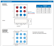
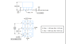
I am inexperienced in soldering, I will use EPC2039 GaN MOSFET and LMG1020 gate driver in my project. MOSFET is pretty small and the package/case is Die. MOSFET pin diameters are given as 208 micrometers. What kind of soldering iron tip should I use in order to be able to solder correctly, how can I decide its thickness.

Do you know of a guide or suggestion on this topic?
 

Attachments

  • epc2039.PNG
    epc2039.PNG
    105.3 KB · Views: 121
  • lmg1020.PNG
    lmg1020.PNG
    60.3 KB · Views: 132

Hi,

no iron. Reflow using hot air or hot plate.

There are many youtube videos for homebrew BGA sodering.

Klaus
 
  • Like
Reactions: Meri96

    Meri96

    Points: 2
    Helpful Answer Positive Rating
I've soldered hundreds of EPC eGaN FETs, soldering irons are basically useless. You need to use a hot air station.

EPC provides instructions which work very well when followed properly.

A few tips, from personal experience:
The preheater isn't always necessary, but is very helpful on larger/thicker PCBs
Smaller devices will be pushed around by the airflow. Use the lowest airflow setting you can get away with.
The tacky flux does help somewhat, but isn't absolutely necessary
You want the pads on the PCB to be tinned, but only with a very thin layer of solder. Too much solder will cause die tilt and you'll get open/shorted joints
Once the solder has started to reflow, don't touch the device. If it moves too much during reflow, remove it and start over
 
  • Like
Reactions: Meri96

    Meri96

    Points: 2
    Helpful Answer Positive Rating
Thanks so much for your valuable suggestions, unfortunately my school's lab does not have a hot air station so I will have to work with another mosfet. Is hot air required for gate driver LMG1020 0.8x1.2mm WCSP case solder, can it be done with soldering iron tip?

As Mosfet, my second choice was IRL80HS120. Package type PQFN 2mm x 2mm. Can this mosfet be soldered without hot air?
 

Hi,

generally you can´t use a soldering iron when at least one pad is underneath the package.

So neither WCSP nor PQFN is meant for iron soldering.

Klaus
 
Yes you need your own wee SMD oven to do little BGAs.
Youtube is the guide as said above
Its also challenging to correctly apply exactly the right amount of solder paste prior to SMD oven-ing it.
 
Got it, then I have to find another mosfet suitable for iron soldering. Is the Si7456CDP PowerPAK® SO-8 sheathed MOSFET suitable for iron soldering?
I am also looking for drivers to drive this mosfet. My circuit has a switching frequency of 10MHz. While searching the high frequency gate driver, I found the EiceDRIVER ™ 1EDBx275F. The operating frequency is given as up to 10MHz. Would it be problematic to use this driver at 10MHz?
 

Your switching period will be just 100ns. May i please ask what topology are you using for this? If you get this working, it will be state of the art.
Elon Musk and co might want to speak with you.
You might be invited to give the next Faraday Lecture, etc
What is your vin, vout, Pout, need for isolation?
 

If you get this working, it will be state of the art.
Elon Musk and co might want to speak with you.
You might be invited to give the next Faraday Lecture, etc

What is the reason for this writing? Did I ask something stupid?
--- Updated ---

Got it, then I have to find another mosfet suitable for iron soldering. Is the Si7456CDP PowerPAK® SO-8 sheathed MOSFET suitable for iron soldering?
"The PowerPAK SO-8 is a leadless package. The end of the lead terminal is exposed copper (not plated) as a result of the singulation process in manufacturing. A solder fillet at the exposed copper tip cannot be guaranteed and is not required to ensure adequate bottom side solder interconnection.
Rework conditions: manual soldering with a soldering iron is not recommended for leadless components."

There is such an expression in the datasheet, I guess I cannot use this mosfeti as I will make my soldering with a soldering iron.
 
Last edited:

What is the reason for this writing? Did I ask something stupid?
No , not stupid. But i hope i can help you to know that what you are doing is not like a starter power supply, and with all respect to you, you sound like a beginner as you are asking about fet soldering. Maybe your teacher is throwing you in too deep i feel. I hope this does not put you off the subject area.

The layout will be really critical for you. I do not think a 10MHz power supply is a good place to start building SMPS. Not at all. I feel sorry for you.

Here is my free smps course for you
https://drive.google.com/file/d/0B7aRNbu3Fes4TU92Mkw3YlA3ams/view?usp=sharing

..but there is nothing in here anywhere near 10MHz switching frequency.
There are virtually no off the shelf power supplies for sale that operate at 10MHz....or anywhere near it.
What sort of input/output capacitors are you going to use?......what will there impedance be at 10MHz?
I hope your teacher has told you of the magnitude of the job that they have offloaded onto you.

Your circuit parasitics are going to mean potentially a lot of debugging for you.
 
Last edited by a moderator:

Thanks so much for your valuable suggestions, unfortunately my school's lab does not have a hot air station so I will have to work with another mosfet.
[/QUOTE]
That's a shame, a decent hot air station costs <$150 USD. I've used this one for GaN FETs with good success.
Is hot air required for gate driver LMG1020 0.8x1.2mm WCSP case solder, can it be done with soldering iron tip?
I have also soldered the LMG1020 and no, it also requires hot air. In fact, it was more difficult than most GaN FET packages.

Using the LMG1020 with a normal MOSFET isn't worthwhile though.
--- Updated ---

Yes you need your own wee SMD oven to do little BGAs.
I've never used an oven for any of these LGA/BGA parts. It's only worthwhile if you're doing large batches and can place them very precisely.
I also never use solder paste with eGaN FETs (only exception is if I have a brand new PCB with ENIC pads).
 

No , not stupid. But i hope i can help you to know that what you are doing is not like a starter power supply, and with all respect to you, you sound like a beginner as you are asking about fet soldering. Maybe your teacher is throwing you in too deep i feel. I hope this does not put you off the subject area.

The layout will be really critical for you. I do not think a 10MHz power supply is a good place to start building SMPS. Not at all. I feel sorry for you.

Here is my free smps course for you
https://drive.google.com/file/d/0B7aRNbu3Fes4TU92Mkw3YlA3ams/view?usp=sharing

..but there is nothing in here anywhere near 10MHz switching frequency.
There are virtually no off the shelf power supplies for sale that operate at 10MHz....or anywhere near it.
What sort of input/output capacitors are you going to use?......what will there impedance be at 10MHz?
I hope your teacher has told you of the magnitude of the job that they have offloaded onto you.

Your circuit parasitics are going to mean potentially a lot of debugging for you.
You are right in all of what you say. I am really a beginner to this field and asked quite a lot of beginner questions. As I progressed, I realized that I was in a really difficult project, it seems that it will get harder and many problems will arise as we progress. I'm just trying to strive and learn something.

I will use a high frequency resistant ceramic capacitor as the input and output capacitor.

I will definitely check your course, thank you for sharing.
 

Yes...your switching period is 100ns......i have done SMPS where thats like the time for the switching transition.
So for 10MHz, your switching transition will have to be very quick so as to avoid high switching losses....but in turn, that is likely to mean
big EMC problems, as well as noise getting into the control.
Even if you do a resonant SMPS, these dont have zero switching losses,.......eg an LLC converter has overlap switching losses pertaining to the magnetising current.
And the VDS transitions in an LLC are very fast still. You will have high dv/dt to deal with....your switching nodes will be very noisy and that noise can pervade round the whole SMPS.
This is why you need to start SMPS learning at low frequency......you may find you have to re-lay out your 10MHz SMPS several times before it works.
 
It really wasn't a suitable project to start with. But I have to finish because of the school. I was told to do this project with reference to the article below. In the article, 30 MHz Resonance SEPIC topology is used. I try to progress and learn something on this path.

You are right, that I made so many adjustments even when I was just design and simulating that when I started PCB design and implementation, editing will be required depending on many problems.

I will take into account what you write as much as I can. Thank you for your valuable opinions.
 

Attachments

  • 2015_APEC_Analysis and Design of A 30 MHz Resonant SEPIC.pdf
    2.1 MB · Views: 87

Thanks for that..... we live in hope that that kind of converter comes to fruition at some point in the future....clearly what they have done there is good for research furtherment, .....but even they would admit that 80% efficiency for a converter that does 15vin, 28vout and 14w = pout is pretty lousy.
 
Status
Not open for further replies.

Similar threads

Part and Inventory Search

Welcome to EDABoard.com

Sponsor

Back
Top