Audioguru
Advanced Member level 7
- Joined
- Jan 19, 2008
- Messages
- 9,458
- Helped
- 2,151
- Reputation
- 4,302
- Reaction score
- 2,008
- Trophy points
- 1,393
- Location
- Toronto area of Canada
- Activity points
- 59,734
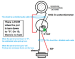
If the mic and pot are connected with ordinary wires then they are antennas that pickup hum.
Shielded audio cable MUST be used.
The lowpass filter is designed to cut 973Hz a little but gradually reduce higher frequencies and still produce 9700Hz.
The lowpass filter is not a filter if it feeds a normal low impedance mic input on an amplifier.
Shielded audio cable MUST be used.
The lowpass filter is designed to cut 973Hz a little but gradually reduce higher frequencies and still produce 9700Hz.
The lowpass filter is not a filter if it feeds a normal low impedance mic input on an amplifier.