Continue to Site

Welcome to EDAboard.com

Welcome to our site! EDAboard.com is an international Electronics Discussion Forum focused on EDA software, circuits, schematics, books, theory, papers, asic, pld, 8051, DSP, Network, RF, Analog Design, PCB, Service Manuals... and a whole lot more! To participate you need to register. Registration is free. Click here to register now.

[SOLVED] Program doesn't start after power cycling

Status
Not open for further replies.

snipex

Junior Member level 3
Joined
May 23, 2016
Messages
29
Helped
2
Reputation
4
Reaction score
2
Trophy points
3
Activity points
284
Hi!

I have encountered a really weird problem that I can't solve.
Problem occurs after I power cycle the microcontroller. I load the program using debug or run in S32 design studio (Eclipse) and after I power cycle the device nothing starts.
Reseting the target without power cycling works fine.
I had a programmer look at my code and it's ok.

I am using NXP's KEAZN64 ARM mircoprocessor.

Do you have any idea what may be cousing this?
 

Hi,

Check
* Power supply voltage
* RESET signal state
* clock frequency
* maybe periferals (FPGA) that need time to start..

* add some "debug code" at the very beginning of the code (port setup, pin toggeling) to see if it really doesn´t start or if program hangs somewhere

Klaus
 

Perhaps your circuit has not any discharging circuit for quick turning-off the RESET pin during power down. In general, putting a diode in parallel with the resistor of the RC is quite enough.
 

I added some debug code that blinks the LED and I got the same result.
Reset signal is connected to PWRGD pin on the DRV8305 driver IC as it says in the datasheet. This however can't be the problem as the previous prototype didn't have this connection and the problem was still there.

Reset signal at power off:
scope_140.png

Reset signal at power on:
scope_142.png

5V at power on:
scope_141.png
 

Hi,

* is the power supply continously and clean 5V for at least one second after power ON?
* is the reset signal continously and clean 5V for at least one second after power ON?
* is the clock frequency stable and is the signal level within specification after power up?
* could the watchdog of the DRV chip cause any problem?
* does the debug LED show any reaction after power up.

Your scope pictures should show the time from power up to (at least) where you expect some activity (often there is a mcu inside delay of some 100ms)

Klaus
 

Sorry for not replying sooner. Here are some more result.

5V power suppy 1s after power ON. Looks clean to me.
scope_191.png

Reset signal 1s after power ON. Looks OK.
scope_192.png

I probably can't measure clock frequency since it's an internal oscillator.
I disabled the watchdog of the driver and the problem remains.
The debug LED shows no reaction.

I created a clean project in S32 Design studio.
The code:
Code:
/*
 * main implementation: use this 'C' sample to create your own application
 *
 */


#include "derivative.h" /* include peripheral declarations SSKEAZN64M2 */

int main(void){
	GPIOA_PDDR |= 1 << 14;
	volatile uint32_t delay = 0;
	while(1){
		GPIOA_PTOR |= 1 << 14;
		for(delay = 0; delay < (1<<20); delay++);
	}

    /* to avoid the warning message for GHS: statement is unreachable*/
#if defined (__ghs__)
#pragma ghs nowarning 111
#endif
#if defined (__ICCARM__)
#pragma diag_suppress=Pe111
#endif
	return 0;
}

The program blinks the led at approximately 1Hz. It works fine when I upload the software but stops working when I power cycle the target.

I found this Errata in the NXP documentation:
Core: Processor executing at HardFault priority might enter Lockup state if an NMI occurs during a waited
debugger transaction

Can this cause problems. I tried with debugger connected and disconnected and the problem is there in both cases.

- - - Updated - - -

Update:

Tried uploading the software to the development board and it works even after power-cycling.
So this can be a debugger issue (I'm using USBDM instead of Segger or PEMicro debugers) or a PCB issue.

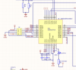
Bellow is the processor schematics:
PCB.PNG
 

Are you perhaps loading the program to volatile storage (i.e., SRAM rather than flash)?
No offense meant: I've done this
 

I am thinking that the device needs a clean RESET signal assertion/unassertion AFTER the 5V power is stablized (we are assuming that the processor is running from the 5V and not from a 3.3V, which could be up even sooner).

Can you briefly assert the RESET signal by hand after the 5V power rail is stable to see if the microcontroller starts?
 
  • Like
Reactions: snipex

    snipex

    Points: 2
    Helpful Answer Positive Rating
Do you give the board enough time for the power-on
reset function (?) to fully reset, itself? Have seen
some POR designs that work great from zero, zero
everywhere but a quick supply drop-and-recharge
doesn't give the internal RC delay element time to
get back to rock bottom. So the POR signal may
not drop, or comes back up with the supply instead
of after the supply is stable enough for the logic to
respond properly.

Try a series of "dark times" (1 sec, 10 sec, 1 min, 10 min)
and see if maybe this is your deal - if it fails to reboot
at 1 sec, 10 sec but is OK at 1 min, 10 min, it may well
be.
 
  • Like
Reactions: snipex

    snipex

    Points: 2
    Helpful Answer Positive Rating
JWHassler:

A programmer took a look at my program and also looked if I was uploading the software to SRAM, but quickly dismissed it because the RAM is too small. The code size is approximately 15kB and RAM size is 4kB.
ps: I don't really know how to upload the code to SRAM :p

ftssolution:

I tried asserting Reset by hand and it doesn't work. I also tried pulling the Reset line to ground before the power supply was turned on with no success.

dick_freebird:

The microcontroller has a built in POR
POR.PNG

I also took a screenshot with the reset and 5V line together:
scope_193.png

Longer dark times also didn't work.

- - - Updated - - -

Edit:

I also measured the !NMI signal at it's always LOW. Could this cause problems?
I tried disabling it but can't seem to find a way to do it, if it's even possible.
 

A few things I see -

The reset line is not asserted after the Power rail is stabilized - it is asserted briefly well before the power rail ahs come up and stabilized, so that is one problem you need to fix with a voltage supervisor or other reset circuit change.

One thing that *might* help you is that you configure the system power management registers to enable the LVD circuit and set the trip point at the higher level at the start of your main(). If the CPU starts to run this will force it to reset, and it will repeatedly do so, until the power rail has come up to at least above the trip point - hopefully things might work better then. From the datasheet:

6.2.2.2
Low-voltage detect (LVD)
This device includes a system to protect against low-voltage conditions in order to protect
memory contents and control MCU system states during supply voltage variations. This
system consists of a power-on reset (POR) circuit, and an LVD circuit with a user
selectable trip voltage, either high (V
LVDH
) or low (V
LVDL
).
The LVD circuit is enabled when PMC_SPMSC1[LVDE] is set and the trip voltage is
selected by PMC_SPMSC2[LVDV]. The LVD is disabled upon entering the stop modes
unless PMC_SPMSC1[LVDSE] is set or in Serial Wire Debug (SWD) mode. If
PMC_SPMSC1[LVDSE] and PMC_SPMSC1[LVDE] are both set, the current
consumption will be higher in Stop mode with the LVD enabled.

Third, if you cannot get the system to reset and boot up again by directly grounding/asserting the RESET pin at any time, then something else is wrong and needs to be addressed with that pin. On some of these chips that pin can function as an IRQ pin if reconfigured by software - are you reconfiguring the pin function in your software?

- - - Updated - - -

Another thing which I forgot to include in the above message - you can also try going to the NXP Community webforum for Kinetis microcontrollers, register, and post your problem there. They are a number of people who are quite familiar with them in that group who may offer advice.
**broken link removed**
 
  • Like
Reactions: snipex

    snipex

    Points: 2
    Helpful Answer Positive Rating
If the NMI is continually asserted, that sure would
muss its mind.
 
  • Like
Reactions: snipex

    snipex

    Points: 2
    Helpful Answer Positive Rating
I have cut the NMI line and the program now starts normally. For some reason it seems to lock up if you assert it at power-up. Thanks to everyone for their help.
Don't know why they wouldn't write this in the datasheet :-? .

But now I have a different problem. The pin that has NMI also has SPI_MISO connected to it and I need that to communicate to DRV8305.
Does anybody know how to get around this?
 

I suppose it's all in where you cut the trace. If NMI is how
the SPI gets the uC's attention, then it's a problem (and
maybe needs to be fixed by a pullup, or intervening logic,
or something). No idea here, about how these pieces are
intended to talk to each other. If NMI and SPI_MISO are
both inputs, and driven from elsewhere, then maybe it's
easily solved by a jumper.
 

Status
Not open for further replies.

Similar threads

Part and Inventory Search

Welcome to EDABoard.com

Sponsor

Back
Top