Continue to Site

Welcome to EDAboard.com

Welcome to our site! EDAboard.com is an international Electronics Discussion Forum focused on EDA software, circuits, schematics, books, theory, papers, asic, pld, 8051, DSP, Network, RF, Analog Design, PCB, Service Manuals... and a whole lot more! To participate you need to register. Registration is free. Click here to register now.

The use of voltage divider to get 0.25V and 200mA

Status
Not open for further replies.

bio_man

Full Member level 2
Joined
Mar 30, 2010
Messages
144
Helped
2
Reputation
4
Reaction score
4
Trophy points
1,298
Activity points
2,698
Hi folks,

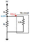
USB provides 5V @ 500mA as we know, I want to get a 0.25V at 200mA using voltage divider as an input source to my circuit but the problem the input resistance of my circuit (Rin) is 1.2kOhms and I can not draw that much current in this case! any tips how can I make this simple source?

I attach a sketch for the circuit
 

Attachments

  • myCircuit.png
    myCircuit.png
    10.8 KB · Views: 95

Impossible. You need 240V to pass 200mA through 1.2K. With 5V from a USB port them most that can flow is (I=V/R) 5/1200 = 4.166mA.

Brian.
 
Or looking at it another way with 0.25V across the 1.2k ohms you will only have 0.21 mA of current not 200 mA
 

thanks all for your feedback. You are right it is not possible to use this circuit and that is why I ask for any suggestion to make it ?

Actually, I considered using the voltage source before I measured the Rin but when I found Rin=1.2k it is clear that this circuit will not work as I wanted

- - - Updated - - -

Maybe he wants 208uA of current, not 200mA.

I want 200mA not 200uA
 

If your input resistance is 1.2Kohms at 0.25V then you do
not need 200mA. Why you "want" it, I'm not prepared to
guess.
 

If your input resistance is 1.2Kohms at 0.25V then you do
not need 200mA. Why you "want" it, I'm not prepared to
guess.

it is really very good question, I am not powering the circuit using this (0.25V, 200mA constant source) but rather this source is considered as an input source to my circuit.

I am trying to emulate a solar cell that has Voc=0.25 and Isc=200mA,, I am not sure if my thinking make sense to you all?
 

Well, you do not get Isc and Voc at the same place. They
are two endpoints of the load-line. I would say that the
1.2K load is close enough to the open circuit condition in
all but the dimmest light (which range of illumination, you
may want to pay attention to if it is supposed to work
indoors). Isc as a function of incident optical power.

Further, your Isc would only be had at 0.0V, which is not
going to run anything. Take a look at the real I-V curve
for your solar cell and the voltage you would get into 1.2K
ohms (might have to do a little Excel work) at your lowest
supported light level, and I think you'll be happy enough
with the simple divider.
 
A solar cell with no load produces 0.5V in full sunlight and maybe 0.25V in a dim indoors room light doesn't it?
My solar garden lights have 4 solar cells in series to make about 2.0V in bright sunlight with no load.
 

Well, we know nothing about the cell specifics. Silicon,
yeah, about 0.5V (give or take, w/ temp and insolation).
But maybe he's a grad student working on II-VI materials,
organic solar cells or something.
 

for achieving the 0.25v, you will required to make the ratio of resistance R2/R1=19.
now you have to decide how much current required to pass through your circuit.
let R1=0.1 ohms and R2=1.9 ohms.then total current will be 2.5 amps and you will be able to get 200ma current through your circuit.
you will required 2.5 amps current input(fast charging like usb 3.0)
DON'T CONNECT THIS CIRCUIT WITH ANY EXPENSIVE DEVICES!:clap: DO YOU KNOW? THE RESISTOR MUST BE RATED WITH HIGH POWER DISSIPATION. DO NOT TRY THIS AT HOME:wink:
hope this question is any educational example:laugh:

- - - Updated - - -

it is really very good question, I am not powering the circuit using this (0.25V, 200mA constant source) but rather this source is considered as an input source to my circuit.

I am trying to emulate a solar cell that has Voc=0.25 and Isc=200mA,, I am not sure if my thinking make sense to you all?

oww! lol :laugh::laugh::laugh::laugh::laugh::laugh:are you thinking to provide power to solar cell!!
solar cell is made for deliver power.:wink: and i am damn sure that this circuit can not convert this low voltage power to be able to supply usb or its rated voltage.
the direction of the 200ma current in fig. tells that you are giving power to solar cell not taking.
you can provide power only to R2.(with solar cell):thumbsup:
 

for achieving the 0.25v, you will required to make the ratio of resistance R2/R1=19.
now you have to decide how much current required to pass through your circuit.
let R1=0.1 ohms and R2=1.9 ohms.then total current will be 2.5 amps and you will be able to get 200ma current through your circuit.
you will required 2.5 amps current input(fast charging like usb 3.0)
DON'T CONNECT THIS CIRCUIT WITH ANY EXPENSIVE DEVICES!:clap: DO YOU KNOW? THE RESISTOR MUST BE RATED WITH HIGH POWER DISSIPATION. DO NOT TRY THIS AT HOME:wink:
hope this question is any educational example:laugh:

- - - Updated - - -


oww! lol :laugh::laugh::laugh::laugh::laugh::laugh:are you thinking to provide power to solar cell!!
solar cell is made for deliver power.:wink: and i am damn sure that this circuit can not convert this low voltage power to be able to supply usb or its rated voltage.
the direction of the 200ma current in fig. tells that you are giving power to solar cell not taking.
you can provide power only to R2.(with solar cell):thumbsup:

it seems you misunderstand my question with your lot of faces in the post!
I don't want to be rude, but if you don't know/misunderstand the concern, NO ONE IS FORCING YOU TO REPLY!

For sure, I am not delivering power to solar cell (who will do that) , I am emulating the solar cell.

People in this forum are seeking serious advices and helpful answers. with your kind of reply, I assure you no one is waiting for it! so please be respectful to be respected.


Thanks anyway for your wired faces!!!
 
  • Like
Reactions: Vraj

    Vraj

    Points: 2
    Helpful Answer Positive Rating
Instead of extensively quoting apparently inadequate posts, why not simply ignore it?

You should use your time to better explain your specification.

Which parameters of a solar cell do you actually want to emulate? A full emulation would involve modeling the solar cell I/V characteristic at variable irradiation levels. The fact that you are only mentioning two corner parameters Voc and Isc suggests that you have either simplified the requirements or didn't yet think about it.

An equivalent circuit of a solar cell can be set up by a diode junction and a current source with additional parallel and series resistors, see https://en.wikipedia.org/wiki/Theory_of_solar_cells#Equivalent_circuit_of_a_solar_cell

However, if the load resistance is known to be as large as 1.2k, as shown in post #1, the equivalent circuit can be simplified to a buffered voltage source with an output resistance according to the I/V slope at the open circuit point.
 

sorry for my funny nature. i will improve myself. sorry for the inconvenience. heart fully sorry,hope you will pardon me.
 

Status
Not open for further replies.

Part and Inventory Search

Welcome to EDABoard.com

Sponsor

Back
Top