Continue to Site
Follow along with the video below to see how to install our site as a web app on your home screen.
Note: This feature may not be available in some browsers.
void main()
{
  int x;
  CMCON = 0x07;
  TRISA= 0x01;
  TRISC  =0x00;
  ANSEL  = 0X01;
  ADCON0=0X81;
  ADCON1=0X30;

     while (1)
         {
          value = ADCON0;
           hun=value/100;
           value=value-hun*100;
           dec=value/10;
                 unit=value-dec*10;
                   cc_1=1;cc_2=0;
                  display();
                  delay_ms(100);
                  cc_1=0;cc_2=1;
                  display2();
                  delay_ms(100);
            }


}#define pin_a PORTC.RC5
#define pin_b PORTC.RC4
#define pin_c PORTC.RC0
#define pin_d PORTC.RC3
#define pin_e PORTC.RC1
#define pin_f PORTA.RA4
#define pin_g PORTA.RA5
#define pin_dp PORTC.RC2
#define cc_1 PORTA.RA2
#define cc_2 PORTA.RA1
unsigned char digit,unit,dec,hun,i,j,value=0;
void display()
{
switch(digit)
{
case 0: pin_a=1;pin_b=1;pin_c=1;pin_d=1;pin_e=1;pin_f=1;pin_g=0;pin_dp=1;
break;
case 1: pin_a=0;pin_b=1;pin_c=1;pin_d=0;pin_e=0;pin_f=0;pin_g=0;pin_dp=1;
break;
case 2: pin_a=1;pin_b=1;pin_c=0;pin_d=1;pin_e=1;pin_f=0;pin_g=1;pin_dp=1;
break;
case 3: pin_a=1;pin_b=1;pin_c=1;pin_d=1;pin_e=0;pin_f=0;pin_g=1;pin_dp=1;
break;
case 4: pin_a=0;pin_b=1;pin_c=1;pin_d=0;pin_e=0;pin_f=1;pin_g=1;pin_dp=1;
break;
case 5: pin_a=1;pin_b=0;pin_c=1;pin_d=1;pin_e=0;pin_f=1;pin_g=1;pin_dp=1;
break;
case 6: pin_a=1;pin_b=0;pin_c=1;pin_d=1;pin_e=1;pin_f=1;pin_g=1;pin_dp=1;
break;
case 7: pin_a=1;pin_b=1;pin_c=1;pin_d=0;pin_e=0;pin_f=0;pin_g=0;pin_dp=1;
break;
case 8: pin_a=1;pin_b=1;pin_c=1;pin_d=1;pin_e=1;pin_f=1;pin_g=1;pin_dp=1;
break;
case 9: pin_a=1;pin_b=1;pin_c=1;pin_d=1;pin_e=0;pin_f=1;pin_g=1;pin_dp=1;
break;
}
}
void main()
{
int x;
CMCON = 0x07;
TRISA= 0x01;
TRISC =0x00;
ANSEL = 0X01;
ADCON0=0X81;
ADCON1=0X30;
while (1)
{
value = Read_ADC( ** );// ADC Channel
hun=value/100;
dec =(value/100) % 10;
unit=value % 10;
digit = dec;
cc_1=1;cc_2=0;
display();
delay_ms(100);
cc_1=1;cc_2=1;
digit = unit;
cc_1=0;cc_2=1;
display();
delay_ms(100);
cc_1=1;cc_2=1;
}
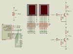
}7 segment 1 7 segment 2 controller
Seg_a Seg_f RC5
Seg_b Seg_g RC4
Seg_c Seg_d RC0
Seg_d Seg_c RC3
Seg_e Seg_dp RC1
Seg_f Seg_a RA4
Seg_g Seg_b RA5
Seg_dp Seg_e RC2i try all things but not get output with adc.what should i do?
please guide me sir.
#define pin_a   RC5_bit

#define pin_b  RC4_bit

#define pin_c  RC0_bit

#define pin_d  RC3_bit

#define pin_e  RC1_bit

#define pin_f  RA4_bit

#define pin_g  RA5_bit

#define pin_dp  RC2_bit

#define cc_1  RA2_bit
#define cc_2  RA1_bit

const unsigned char Drive_Segment[10] = {2 , 158, 36, 12, 152, 72, 4, 30, 0,8};
const unsigned char Drive_Segment_1[10] = {72 , 237, 152, 137, 45, 11, 10, 233, 8, 9};

// For common cathode display:
// Drive_Segment[10] = {253, 97, 219, 243, 103, 183, 191, 225, 255, 247}
// Drive_Segment_1[10] = {183, 18, 103, 118, 210, 244, 245, 22, 247, 246}

unsigned char unit,dec,i;
unsigned short  value, SendVal, digit1, digit2;
float voltage, real_value;
unsigned int ad_value;
 void send() {

          pin_dp = SendVal & 1;             // bit 0
        pin_g = (SendVal & 2) >> 1;      // bit 1
        pin_f = (SendVal & 4) >> 2;      // bit 2
       pin_e = (SendVal & 8) >> 3;      // bit 3
        pin_d = (SendVal & 16) >> 4;     // bit 4
        pin_c = (SendVal & 32) >> 5;     // bit 5
        pin_b = (SendVal & 64) >> 6;     // bit 6
        pin_a = (SendVal & 128) >> 7;     // bit 7
        }


void main()
{
  CMCON = 0x07;
  TRISA= 0x01;
  TRISC  =0x00;
  ANSEL  = 0X01;

PORTA = 0xFF;
PORTC = 0xFF;

 // For common cathode display:
//PORTA = 0x00;
//PORTC = 0x00;

delay_ms(500);

 do {
 ad_value = ADC_read(0);
 voltage = (float) ((float) ad_value * .00488);
real_value = (float) voltage;


 value = real_value * 10;
 dec = (char)value/10;
 unit = (char)value%10;
 digit1 = (char)Drive_Segment [dec];
 digit2 = (char)Drive_Segment_1 [unit];
 for (i = 0; i< 10; i++) {
 SendVal = digit1;
 send();
 cc_1 = 0;
 cc_2 = 1;
 // For common cathode display:
 //cc_1 = 1;
 //cc_2 = 0;


 delay_ms(2);
 cc_1 = 1;
 cc_2 = 1;

 // For common cathode display:
 //cc_1 = 0;
 //cc_2 = 0;

 SendVal = digit2;
 send();
 cc_1 = 1;
 cc_2 = 0;

 // For common cathode display:
 //cc_1 = 0;
 //cc_2 = 1;

 delay_ms(2);
 cc_1 = 1;
 cc_2 = 1;
 // For common cathode display:
 //cc_1 = 0;
 //cc_2 = 0;
                     }

           } while (1);

       }