Okada
Banned
Yes, that is the formula for LC low pass filer calculation.
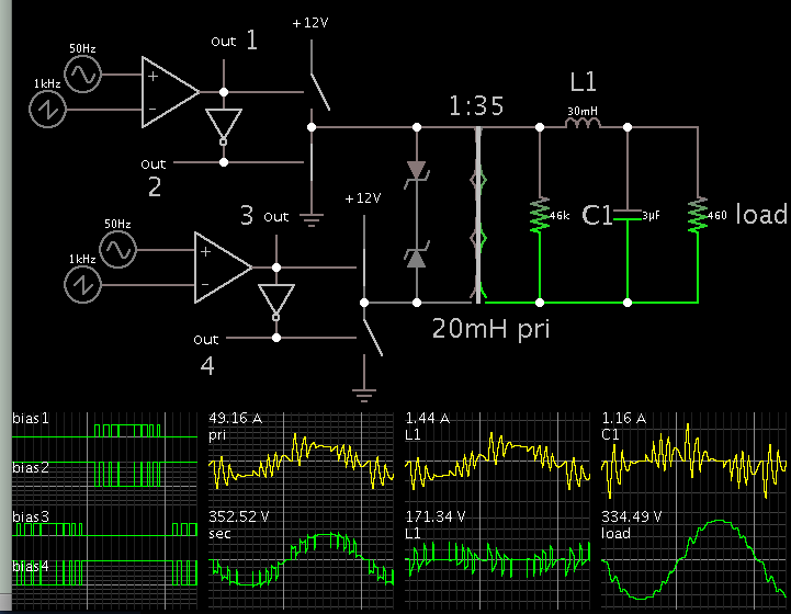
Attached is the Inverter which I am designing. Filter I will finalize after I build the hardware and apply different loads. I will provide option for LC and Pi filters on the PCB but I will only put them after testing the signals.
You can see that I have not used IR21xx device for driving FETs because I have used FDP8440 Mosfets and it can conduct 80A at 4.5V Vgs. I will apply 5V to gate. This simplifies the circuit.
For battery charging I am using a separate transformer because I read somewhere on the net that if same transformer is used for Output and also for charging then due to difference in currents the transformer windings will get fried and the enamel coating will break and the transformer will short circuit.
Here what I found regarding filter design.
https://electronics.stackexchange.com/questions/144467/lc-low-pass-output-filters-for-inverters
Attachments
Last edited: