Continue to Site

Welcome to EDAboard.com

Welcome to our site! EDAboard.com is an international Electronics Discussion Forum focused on EDA software, circuits, schematics, books, theory, papers, asic, pld, 8051, DSP, Network, RF, Analog Design, PCB, Service Manuals... and a whole lot more! To participate you need to register. Registration is free. Click here to register now.

AC Wheatsone bridge equivalent impedance at AC

Status
Not open for further replies.

vitoa

Member level 2
Joined
Jul 28, 2015
Messages
52
Helped
4
Reputation
8
Reaction score
4
Trophy points
8
Activity points
522
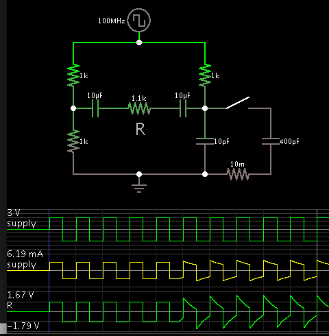
AC Wheatsone bridge equivalent impedance at AC 80 MHz

Hi, need some help to calculate equivalent impedance of this bridge and resistors needed at 80MHz
Capacitance Cx is going to be the variable.

w_bridge_measure_c_2.png


Checking this theory **broken link removed**

R1/XC1 = R2/XCx at equilibrium

Cx goes from 10pF to 1nF
At 100Mhz Xc goes from 1,6ohm to 160ohms

Equivalent resistence is on this theory:

**broken link removed**

I'm going to use instrumentational amplifier to measure difference A to B. Input resistence is 1,1KOhm
So this is 1,1Kohm is equivalent to R5 in circuit.

Oscillator source can goes to minimum 500ohm impedance load. 3Vpp @ 80MHz

How to match this bridge to output of oscillator with 500ohm output impedance?
 

I'm not aware of an instrumentation amplifier working at 80 MHz. Did you consider a specific type?

I believe, the circuit can illustrate the concept but can be actually used at 80 MHz.
 

Instrumentational amplifier has BW DC to 500MHz
 

I believe you have hit on a good approach, namely to explore laboratory-style methods. It gets close to the principle of operation. Later you can determine whether, or which, IC is available that will do this task.

The capacitive type of measurement might work. In addition it might also pay to consider magnetic measurement, and electromagnetic (photon) measurement.

For each type of field, you want to try various frequencies. I suppose it would be ideal if there were some wavelength that is unique to water. Either a capacitive or magnetic or electromagnetic type of field. The frequency might be a teraHertz, or 10 tHz, or 100 tHz. Then you would measure primarily presence of water. However I know of no such oscillator which can sweep such high frequencies.
 

This is the simplest approach for minimal components for volumetric water content sensor.
Frequencies only reach water are 80MHz-100Mhz range more than that water mineral ressonates causing unacurate readings.
Its possible to identify minerals across spectrum, but need to do sweep until Ghz frequency.
There are some GHz oscillators but not THz..
 

IMG_4838[1].JPG

I need to match this bridge to a 600ohm network. AD8307 is an instrumentational amplifier to measure middle of bridge.
Z probe goes up to 1-200ohm.
Instrumentational amplifier AD8307 has an impedance of 1,1Kohm
Thevenin equivalent maybe needed? **broken link removed**

How to calculate R and Rv? to get a match 600ohm bridge to source
 

I believe one aim is to send sufficient Amperes through the probe, so that it generates voltage swings which are wide enough to be measured.

Z probe goes up to 1-200ohm.

This seems like an enormous spread of values. Do you mean 100-200?

Anyway a sensible R value is the geometric mean between the maximum and minimum. It should give you a usable voltage swing. You also need to have sufficient Amperes flowing in the circuit, in order to operate the probe's capacitance, and to generate usable volt readings.

There may be a phase difference between the center nodes of the bridge, created by capacitive reactance.
 

I found return loss bridge matched to 50ohm circuit, so to get 600ohm impedance use 600 ohm resistors?
This is the same circuit principle.

@10_May_2016.JPG

example brdge for 50ohm impedance.jpg

How to match this bridge to 600ohms? AD8307 has an impedance of 1,1Kohm
 

In your frequency range you have to pay attention on another parameters of elements, not only DC parameters. Except real parts there are imaginary parts of impedance too.
In such case you should start think about elements as their equivalent circuits. For instance it is possible that your capacitor in such freq work even as inductor.
It you would like to balance bridge you should use R and very good quality C like in Schering bridge, or maybe Wien parallel bridge, depends on sample parameters. so in my opinion you should learn more about AC bridges.
I think match of impedances it is yours smallest issue
 
  • Like
Reactions: FvM

    FvM

    Points: 2
    Helpful Answer Positive Rating
I've done minor change to bridge and is working fine. instead of connection one terminal of probe to ground I connected to other input of amplifier. Check this paper. **broken link removed**
 

From my experience with soil humidity measurements your trial is very interesting. But you will find some problems.
In my opinion your circuit isn't Wheatstone bridge, maybe even it isn't bridge. As I found you even don't try to balance it. The main advantage of your circuit is that it works ;) and it is the most important.
From the beginning. From the picture I found you use tantalum capacitor. Check your cap datasheet, but most of tantalum cap are capacitor up to 1 - 10 MHz. Above there is inductance dominant. Fortunately you have used two similar caps, so for balance it doesn't matter. But I would thought because there is high temperature dependency in such cap parameters.
You don't care about balance of bridge or even you are out of balance, so you don't have to care about imaginary parts of impedance. For now you have to think about final acquisition method, because your meter is the part of circuit and we don’t know what happened with signal. In my opinion you measure something proportional to modulus of impedance with integration constants of a few Hz (DC meter range ???)
I think you should read more about soil humidity measurement methods – especially FDR and TDR. The most important problem is that on such frequencies there are scale problems – sample should be big enough to get proper results, so with small pile of soil you get quite different results than on the field. So you should perform measurements in at least flowerpot (from dielectric material !!!).
From the beginning you should make board for your circuits, because parameters of your circuits depends on “geometry” – with “spider” circuit you can get unrepeatable results.
If you would like to make humidity indicator, I think you have one. Now you should perform measurements in different humidity check characteristics – especially linearity and repeatability with different soils.
If you plan to make humidity meter you should carefully rework your circuit and chose elements to work near bridge balance (real and imaginary parts) to avoid nonlinearity and even saturation.
From my point of view, for now match of circuit impedance it is your smallest problem
 

Hi KamW, I can't call it now bridge because is not a bridge measure. First experiement with one end of probe connected to ground, the voltage only get a difference of about 200mV wet to dry, when changed probe ground pin to other input of amplifier ther circuit started working as I expected but not as I planned, not in the original configuration bridge. So this concept is not anymore brige but is amplified returned signal. Maybe compare to a resistor divisor and amplifier is measuring voltage drop on probe. Z probe goes from 1.6ohm to 160ohm reactance capacitive.
Tantalum caps are going to be replaced by ceramic ones. This were first capacitors I had for testing.
I added second Rx in order to get bridge configuration but voltage measured decreased range, so I removed it again.

I have tested on some plant pot's , measurings were very fine and precise. Even more than any sensor I've tested before at low MHz
For first prototype "spider" geometry is fine because not much worry about precise frequency or any frequency drift due to big components.Final design will be in smd. For example FM oscillator keep drifting with temperature, needs vco.
I've assembled one spider 2W FM transmitter and working fine, but not so precise as smd. Frequencies above hundred MHz not possible to build "spider" because the components will act as indutances.


This is the new circuit. 1,1Kohm is impedance of AD8307
new circuit.jpg

I'me doing repetitve soil measures in order to get conclusions.
 
Last edited:

Circuit was working at 40Mhz because div connector was open. Now set at 80MHz, voltage output range is going to half. Maybe tantalum capacitors are blocking some 80MHz signal.
Dont know why lost voltage range. Now lower interval 300mV instead of 700mV interval dry to wet previosly at 40MHz
 

In the bridge configuration you should get signal of sine wave shape (assuming you have sine excitation) which on simple meter with DC range you should measure nothing .
You should use some kind of rectifier because I am not sure if your meter in AC range could detect signal of such freq.
When you ground signal you probably deform your signal and you get DC component of signal which is measureable by simple mutimeter.
When you have finally changed frequency, you have changed shape of signal, and you could read quite different value of DC voltage on mutimeter

- - - Updated - - -

I think you shoult test your voltmeter for ability of such freq measurements
 

Now seems I'm working in the dark because my 100MHz oscilloscope is not available anymore.Can't see wave form, but is oscillating at 80MhZ. I'me getting porportional output DC according the impedance of probe.
A simple measuring capactitance at probe with capacimeter, 10pF free air and 1000pF wet media. 250pF is perfect humidity soil. Maybe I need to redesign capacitive probe to less capacity max 300pF at wet media instead 1000. this will give a more precise range for soil applications. 10-250pF aprox impedance at AC 8ohms to 200ohms probe variance.

Capacitive probe is very sensible. capacity goes up to 200pF at hand touch. Sensor is detecting range up to 8cm surrounding. Similar to this operation:

Figure-2-Principle-of-operation-of-the-FDR-sensor-left-6-7-9-and-idealized-volume.png

When changed from 40MHz TO 80Mhz the voltage DC out went to half interval. This because impedance of probe goes to half when frequency doubles. So if frequency doubles, probe capacity must be less. Maybe half 5pF-300pF in wet media.
 
Last edited:

I wonder I have not seen plane pcb probes for humidity measurements work on rf. most of probes it were two skewer with quite high distance between.
There are a few reason. one of it it was small cap. but in such freq I would care about edge effects. So I would prefer two rods configuration of electrods than plane.
Some time ago I have worked on similar soil humidity meter with miniature thick film electrodes and with small probe of about 0.5 cm diameter I have seen influence of standard soil sample container with about 8 cm diameter.
Let's look at your picture - acording to skin effect field distribution should be quite different.
 

Let's look at your picture - according to skin effect field distribution should be quite different.
I don't think that skin effect is the major problem here. The field picture is in fact different, already according to elementary electrostatic law.

Electrodes with sharp edges involve increased field strength and sensitivity to media inhomogeneity. Round electrode shape is always preferred.
 

Some one to help me solve this wheatstone bridge and calculate R's
Any quick simple simulation if possible Thanks

IMG_4936.JPG
 

Here is a simple simulation.

Your supply waveform looks like a square wave, so I used that. However I had the idea you intend to use a sinewave.

The run started with the switch closed, so the 400pF capacitor was in circuit.
Halfway through the run the switch was opened, leaving only 10pF.


Your supply is rated to provide 6mA (3V / 500 ohm). Resistor values were adjusted accordingly.
 

Status
Not open for further replies.

Part and Inventory Search

Welcome to EDABoard.com

Sponsor

Back
Top