Continue to Site

Welcome to EDAboard.com

Welcome to our site! EDAboard.com is an international Electronics Discussion Forum focused on EDA software, circuits, schematics, books, theory, papers, asic, pld, 8051, DSP, Network, RF, Analog Design, PCB, Service Manuals... and a whole lot more! To participate you need to register. Registration is free. Click here to register now.

Offline Switch Mode EV chargers should be made of paralleled <3kW modules?

Status
Not open for further replies.
Yes, anyway I definetely think that there is some situation with mains connected Switch Mode Power Supplies, whereby they can become “victim” of the terrors of the mains, be that transients or whatever.
I think that this affliction more concerns those switching supplies which also have an Earth connection.
Very little is publicly known about this, because obviously those companies who know much about it guard it closely as their intelligent product, -their little “earner”.

I remember when I worked at the electric drives place described above, the “reason for failures” document was an absolute top secret document, and no-one was even allowed to discuss it. It was strange because we had an entire section of engineers repairing and diagnosing blown drives, and yet, if any member of staff ever asked about drive failures, they were always told “We have a zero failure rate!”. –Which was strange being told that when you could see the large “repair section” working all day long.

So yes, I believe that it is totally pointless designing and marketing high power single stage Electric vehicle chargers which are expensive to do. –Just do an Electric vehicle charger as a load of low power, filthy cheap, paralleled modules.
 

Another reason why offline, high power Electric Vehicle chargers should not comprise a single, expensive , high power stage is because inevitably such a power supply will be air cooled, and thus its enclosure will have vent holes in it. (any other form of cooling for such a power supply would be very very much more expensive)

-And the point is, that if you have air holes in an SMPS enclosure, then your Ingress Protection (I.P.) rating tumbles down, and your SMPS becomes very vulnerable to a build up of dust particles causing problems in the power supply…..not only that , but moisture also can ingress into the power supply, and we all know how bad moisture is inside power supply enclosures.

So basically, high power electric vehicle chargers should be comprised of multiple , fithy cheap, air cooled, paralleled modules.

I remember working at a UV LED curing place that made the high power LED drivers for the UV curing heads. The LED drivers were in vented, air cooled enclosures. Many of the failed units that used to come back to us literally looked like they had been dropped into a mud bath, -they were so utterly caked in dust.

There are currently a large number of companies making “all singing and all dancing” expensive electric vehicle chargers with expensive, complex topologies….all of which will succumb to failure from mains transients or ingress of dust/moisture. This can be prevented by extremely expensive measures, but that simply isn’t worth it.

-However, if some company has managed to fool some “Industry and skills” organisation into giving them enormous funding to make some “all singing, all dancing” electric vehicle charger, then I suppose you want to keep ‘milking’ the lavish funding, and keep designing something that’s practically a waste of money.
 
Last edited by a moderator:

Another reason why offline, high power Electric Vehicle chargers should not comprise a single, expensive , high power stage is because inevitably such a power supply will be air cooled, and thus its enclosure will have vent holes in it. (any other form of cooling for such a power supply would be very very much more expensive)

-And the point is, that if you have air holes in an SMPS enclosure, then your Ingress Protection (I.P.) rating tumbles down, and your SMPS becomes very vulnerable to a build up of dust particles causing problems in the power supply…..not only that , but moisture also can ingress into the power supply, and we all know how bad moisture is inside power supply enclosures.

I have only ever seen water cooled chargers on commercial EV's (with exception for conversions)

Here's one for a leaf:

125.jpg
 
  • Like
Reactions: treez

    T

    Points: 2
    Helpful Answer Positive Rating
Thanks, yes, the chargers that exist actually on the vehicles are a different story, they need to be long lasting and expensively made..and prefereably as small as possible.
I should have said that I am speaking of the chargers which exist in the car parks etc.

I actually doubt that the on-board chargers are generally as high power as the fixed chargers that exist in the car parks, and that get connected up to the cars as they drive up to them.
 

yes, i am not familiar with that term EVSE, but i mean the stationary charger that connects to the car, but doesnt drive off with it.
 

yes, i am not familiar with that term EVSE, but i mean the stationary charger that connects to the car, but doesnt drive off with it.

Those aren't 'chargers' they are supply equipment.

The only thing they do is indicate the available power and provide it, trough an AC contactor, if no error is present at either end.
Its up to the vehicle charger to do the actual charge once it receives the AC supply and also to draw the correct amount (otherwise the breaker on the EVSE trips)

CHAdeMO standard is an actual charger but these are 40-200KW, used on motorways.
 

Re: Offline Switch Mode EV chargers should be made of paralleled &amp;lt;3kW modules?

surely they are not going to put 50kW chargers on a car?
I thought the "on-car" chargers were just "desperation" measures, -to be used when you get "caught out" away from a proper, stationary charging point?

The following is for EV charging, and as you can see, its not for mounting on a car....its 60kW total. (twelve 5kw modules)
**broken link removed**

- - - Updated - - -

The following small 3kw charger, is , i thought, an "on-car" charger...just 3kw...
**broken link removed**

...i certainly cant see an electric sportscar having a 50kw charger on it?...it'd be too heavy for a sportscar.

- - - Updated - - -

I agree the motorway chargers can give 40-200kw, but in actual reality , such is the poorness of EV batteries, that it is very very unlikely that they will actually be charged at that rate for much of the charging time……the batteries heat up whilst being fast charged, and the charger then senses the battery overvoltage, and pegs back its charge rate so as to stop the EV battery from blowing up…..so in reality, a charger rated for 200kw, will only end up actually charging the EV at about 3kw for most of the time. That’s the reality of it.

The easiest way to point this is to mention that whatever you see as stationary chargers (CHAdeMO being the exception) is just an AC outlet controlled by the car. They are not chargers, hence the name EVSE - Electric vehicle supply equipment. The charger is on the car and dictates how fast one car charge (typically 6 or 7KW), as long as the EVSE can supply it

Some companies install those at home. They are nothing more than a electronic PCB with a contactor, a plug and a RCD.

CHAdeMO is in fact a charger, but not all EV's support it. A leaf connected to a CHAdeMO unit charges at a rate of 25KW until the battery reaches 80% SoC.

Dedicated chargers are custom modifications which require a output voltage and current to match the particular vehicle. These are not standard and are often meant for conversions. The most a regular user can do is instal a CHAdeMO charger as this one
 
Last edited:
  • Like
Reactions: treez

    T

    Points: 2
    Helpful Answer Positive Rating
Are all EV chargers isolated with a transformer from mains. I have seen EV chargers construction articles on electric car building sites that use no isolation.
 
  • Like
Reactions: treez

    T

    Points: 2
    Helpful Answer Positive Rating
Yikes !

And what do suppose might happen if some guys metal car ends up at full mains voltage with respect to the ground ?
 
  • Like
Reactions: treez

    T

    Points: 2
    Helpful Answer Positive Rating
Re: Offline Switch Mode EV chargers should be made of paralleled &lt;3kW modules?

I found my old notes. More info on non-isolated EV charger

Original build of this charger is here.

https://www.diyelectriccar.com/forums/showthread.php/10kw-60a-diy-charger-open-source-59210.html


old website

https://web.archive.org/web/20121129064627/http://www.emotorwerks.com/cgi-bin/VMcharger.pl?


Schematics and PCB layout are here but you have to use Express PCB to open them. If someone here has Express pcb loaded they could give us a screen shot.

https://emotorwerks.com/VMcharger_V12P/


Some talk of the charger being non-isolated is here.

https://endless-sphere.com/forums/viewtopic.php?f=14&t=30974&p=448520&hilit=VMcharger#p448520


"Next steps / future versions"
"Develop an isolated version"

https://web.archive.org/web/20121129064632/http://www.emotorwerks.com/cgi-bin/VMcharger_V9.pl
 
Last edited:

But no isolation did not bother anyone on the thread, and it was popular and long.
May be because the idea is just too odd. As for me, isolation is taking as granted. I expect the non-isolated charger to trip the isolation fault monitor of modern E-cars.
 

Re: Offline Switch Mode EV chargers should be made of paralleled &lt;3kW modules?

Cant say commercially. I would certainly not isolate mine for cost and efficiency reasons.

This might not be immediately obvious until one realizes that most vehicles nowadays have 300 and 400V battery packs and as such, the high voltage section is already suitably isolated from the vehicle chassis.

For a technician working on the vehicle HV section isolation is required. I'm sure anyone trained would be aware of this and connect the vehicle and diagnostic equipment to an isolated supply.

- - - Updated - - -

I found my old notes. More info on non-isolated EV charger

Original build of this charger is here.

https://www.diyelectriccar.com/forums/showthread.php/10kw-60a-diy-charger-open-source-59210.html


old website

https://web.archive.org/web/20121129064627/http://www.emotorwerks.com/cgi-bin/VMcharger.pl?


Schematics and PCB layout are here but you have to use Express PCB to open them. If someone here has Express pcb loaded they could give us a screen shot.

https://emotorwerks.com/VMcharger_V12P/


Some talk of the charger being non-isolated is here.

https://endless-sphere.com/forums/viewtopic.php?f=14&t=30974&p=448520&hilit=VMcharger#p448520


"Next steps / future versions"
"Develop an isolated version"

https://web.archive.org/web/20121129064632/http://www.emotorwerks.com/cgi-bin/VMcharger_V9.pl

Be aware of the number of bugs on that charger. There's a member: PS_Tech_paul which has been carrying out a number of modifications to that charger and he explains many of these here: https://www.diyelectriccar.com/forums/showthread.php/analyzing-troubleshooting-fixing-emw-10kw-diy-158057p5.html

I'm not a big fan of the approach on its own. I once suggested the use a buck PFC approach, which would be easy to implement and dispense the use of the expensive bulk electrolytic capacitors/pre-charging circuitry. Such idea was never implemented, but a new 25KW version for HV batteries which has this feature has been released

https://emotorwerks.com/

The other thing is using an arduino between your $10K Battery pack an the mains. I'm sure a suitable DSP processor or at least an MCU with a power stage controller would have been a wiser choice.
 
  • Like
Reactions: FlapJack and treez

    T

    Points: 2
    Helpful Answer Positive Rating

    FlapJack

    Points: 2
    Helpful Answer Positive Rating
Re: Offline Switch Mode EV chargers should be made of paralleled &lt;3kW modules?

Cant say commercially. I would certainly not isolate mine for cost and efficiency reasons.

This might not be immediately obvious until one realizes that most vehicles nowadays have 300 and 400V battery packs and as such, the high voltage section is already suitably isolated from the vehicle chassis.

This is a surprise to me. Are you saying that the 400v battery pack does not share a common ground with the automobile frame? Are all EV's made this way?
 
  • Like
Reactions: treez

    T

    Points: 2
    Helpful Answer Positive Rating
Re: Offline Switch Mode EV chargers should be made of paralleled &lt;3kW modules?

This is a surprise to me. Are you saying that the 400v battery pack does not share a common ground with the automobile frame? Are all EV's made this way?

They are and should remain isolated.

The inverter creates a virtual 0V at 1/2 battery voltage to be able to create the 3 ph sine or trapezoidal wave output (+VE and -VE) for the motor. This document is a good read to understand how it works: https://ww1.microchip.com/downloads/en/DeviceDoc/70062E.pdf (figure 15-13 shows the electrical diagram)

The traction motor is earthed to the chassis (not grounded), whenever there is a high voltage insulation fault it will either be connected to battery (HV+) or battery (HV-). Since the voltage is floating it wont cause harm to the user, but this potential is used by the ECU to detect a failure in the motor insulation or, more rarely, the DC-DC converter.

I'm guessing most EV's aren't on the market long enough to have much of an history, but hybrids are. The Prius is known for trowing (among others) fault codes 526 and 613 whenever there's an insulation failure on the motor winding's. It requires replacement of the transaxle.
 

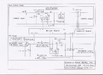
Schematics and PCB layout are here but you have to use Express PCB to open them. If someone here has Express pcb loaded they could give us a screen shot.
For the incurably curious, here is the power circuit topology:
Vehiclecharger1.jpg
 

Status
Not open for further replies.

Part and Inventory Search

Welcome to EDABoard.com

Sponsor

Back
Top