Continue to Site

Welcome to EDAboard.com

Welcome to our site! EDAboard.com is an international Electronics Discussion Forum focused on EDA software, circuits, schematics, books, theory, papers, asic, pld, 8051, DSP, Network, RF, Analog Design, PCB, Service Manuals... and a whole lot more! To participate you need to register. Registration is free. Click here to register now.

Shifted Resonant Frequency between HFSS simulation and PCB antenna

Status
Not open for further replies.

BiNa2605

Full Member level 3
Joined
Sep 1, 2015
Messages
179
Helped
6
Reputation
12
Reaction score
4
Trophy points
18
Location
VietNam
Activity points
1,357
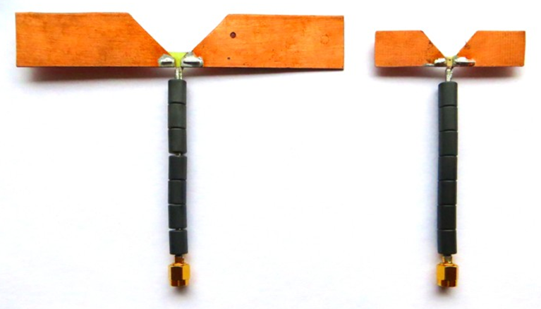
I simulated the UHF antenna in HFSS, expected resonant freq. is 915MHz. The results shows very promising (S11~-35dB). But when I make a PCB, the figure below, the result is implemented by using Network Analyzer, the resonant freq. shifted from 915MHz to ~1.9GHz.

In the simulation file, I chosed FR4 as a material, is it right?. Does anyone get me some recommendations for that? What could I can change for achieving a good result?

-Applying matching circuit.
-Make a new one. How can I calculate exactly?

Thanks
P_20160311_211750.jpg
P_20160312_102613.jpg
S11_Return_Loss.jpg

- - - Updated - - -

This is the HFSS project file.
 

Attachments

  • 915Mhz_1.rar
    43.1 KB · Views: 89

Whatever you simulated before, it's impossible to measure the antenna with an asymmetrical cable connection without a balun or other means to isolate the cable from the antenna.

Did you include the thin traces in your simulation? How about the circuit below the SMA jack, has it been disconnected for the antenna measurement?

Some suggestions about suitable balun designs in previous threads, e.g. https://www.edaboard.com/threads/273612/#post1173201
 
I measured again with the balun cable.
P_20160313_165944.jpg
The circuit below the SMA jack is Energy Harvesting circuit. In the previous picture, I connected with the antenna so the result did not show a reliable result.
 

Does anyone have a sample dipole planar or microstrip UHF antenna working at 915Mhz? I need a good performance antenna to harvesting enery for my circuit.
In my experimences, when I designed 8 stages of multiple voltage using RF diode HSMS-2852, the output voltage I get just 1.62V (~1 meter from the 1W RFID reader). In the other hand, the P1110 (energy harvesting IC of Powercast) is intergrated in the commercial board (a good performance antenna at 915Mhz) can get 1.62V (over 6 meter). Now I want to apply the output voltage from energy harvesting for supply to sensing circuit (MCU+sensor), what do I need to pump voltage to 3V, at least 5mA to operate the circuit? I search on the Internet and discover LTC3105 IC boost (just 200mV input, 3.3V for LDO), it is possiblility?
I appreciate any suggestion and recommendation.
 

Shouldn't you evaluate impedance and performance of your rectifier circuit with a signal generator first?
 
It is very easy to make well performing well matched dipole antenna for 900MHz ISM band.
Cut piece of double-sided PCB 20-25mm wide 145 - 150mm long. Mark middle of the length on both sides. Draw middle line across antenna width. Remove copper strip on both sides 2 - 5 mm wide along middle line. Make sure removed strip is symmetrical to middle line you drew earlier. Do this on both sides of PCB. Cut notch in PCB, ~90 deg, again, symmetrical to middle line as it is shown on photo. leave ~5mm PCB width so it will not easy to break. Connect together copper on each side of PCB. How - make hole in each half close to middle line where copper is removed; push wire through; solder on each side. Take cable you plan to use with antenna. Use thin coaxial cable: RG316, RG178 - the thinner the better. (I use rigid coax.) No need balun or choke for tuning as you will keep cable perpendicular to antenna. Calibrate NA at the edge of the cable: O/S/L. Solder coaxial cable to antenna: central conductor to one side, braid to another side. Make small solder joints. Make sure coax connected symmetrically to antenna perpendicularly to it's edge. Refer to attached picture. Place antenna in such way that it sits in the air, no metal around. Make sure cable routed perpendicularly to antenna. (I usually place antenna horizontally, mounted it on narrow styrofoam blocks, cable runs down). On Network Analyzer you should see deep resonance at ~850MHz. Gradually shorten length of your antenna cutting away ~1 mm at a time from each side so your middle point remains in the middle, until your resonance moves up to 915 MHz. You are done!
If all done right you should have ~100MHz Bandwidth below -10dB return loss (way wider then 900 ISM band), gain 2dBi efficiency > 95% when copper is fresh (efficiency will go down a little when copper oxidizes.)


picture shows two antennas tuned for different bands.
I hope this helps.
 
  • Like
Reactions: FvM and BiNa2605

    BiNa2605

    Points: 2
    Helpful Answer Positive Rating

    FvM

    Points: 2
    Helpful Answer Positive Rating
That's right Sir, I lack of a lot of experiences. Now I evaluate impedance and performance of my rectifier circuit (RC) first. I measured the output voltage of my RC, it is just 1.7V, while the commercial circuit is 4.1V with the signal generator.
About impedance, I just measure that value (seperate with Antenna).
P_20160322_171511.jpg
So what I do next Sir?
 

Attachments

  • Matching Circuit for EH.PNG
    Matching Circuit for EH.PNG
    46.7 KB · Views: 132

Your Detector Impedance is ~ 6 Ohm - way too low to connect it to dipole. What side of detector do you measure - RF? You need to work on match to make sure it is 50 Ohm if you want to use it with 50 Ohm antenna.
 
So I need to add a resistor in series to increase the impedance? I am not have much knowledge about that field. I am still not understand, why it is 50Ohm? Do I need concern about the impedance of microstrip dipole that I designed.
Your recommendations are very helful.

- - - Updated - - -

I used that antenna for RFID passive tag.
 

Not resistor. If you add resistor all energy antenna gathers will be lost in resistor. You have to match it with inductors, capacitors, sections of transmission line or transformer so where it is connected to Antenna (RF input) it should measure 50 Ohm. Matching is a procedure you need to study. In brief i would disconnect match you got now (inductor and two sections of transmission line); measure impedance of only the diode (and when doing that make sure video out port is connected to following circuit); design matching network so measured impedance is transformed to 50 Ohm.
Also dipole is balanced antenna and circuit you want to connect to it is single-ended. It will work to some degree but not the greatest.
 

Measuring detector impedance with VNA can be misleading because it's strongly depending on the input voltage. It can work if the VNA output level can be set to a value similar to expected rectifier operation point. Otherwise it would be better to perform load pulling with a variable matching network and a generator.
 

I looked at your detector circuit - it looks like it is taken from data sheet for the diode. If so you should measure 50 Ohm at RF input - the people who made this circuit know what they do I assume (and you can confirm with data sheet that RF input should be 50 Ohm). And if you measure 6 Ohm on RF input i recommend troubleshooting your circuit so it is so different with their.

- - - Updated - - -

FvM I personally do not do load pulling anymore - not in last 10 years. Network Analyzer does it all for me.
 

I wonder how the detector circuit in post #7 is related to the original 8-stage voltage multiplier in post #1. Obviously the input impedance is completely different.

The impedance matching in post #7 is for a small signal rectifier, it's not necessarily the same for large signal. There should be a real load impedance when testing the rectifier.

I would also suggest to choose a reasonable frequency range for S11 smith diagram. 300 kHz to 3 GHz is more or less useless to visualize the impedance.
 
I measure the impedance and return loss of my Antenna (without 8-stage voltage multiplier). I still don't understand. With VNA the input impedance is 50Ohm and in real antenna (the impedance, it will be different).
The figure in #7, I got from the datasheet of RF diode (they recommend).
S11 My Antenna.jpg
Impedance Matching.jpg
AndreyG, 6Ohm is the impedance of 8-stage multiple voltage. I used HSMS-2852 and 3.3nF for capacitor.
The impedance voltage of RF input is 19.229Ohm.
So now I will study matching circuit between RF input and 8-stage multiple voltage, is that right?
 

Not sure I understand what you say. What is on pictures - that's how you measure antenna? It looks tuned too low. How you hold your antenna when you measure it? It is best to place it where you want to be in working conditions or in free space - support it with pieces of styrofoam or hang on something.
Also FvM is right - you cannot see anything on Smith Chart. Limit the bandwidth on Network Analyzer. Sat it to, say, 500MHz to 1GHz.
Re - detector - I am not clear what you measure and which detector you use. Explain yourself clearly, provide NA plots.
 
  • Like
Reactions: FvM

    FvM

    Points: 2
    Helpful Answer Positive Rating
I write my self clearly in the ppt file. I hope you can spend a little bit of time to kick me out of that, I really want to understand it.
 

Attachments

  • My Target.rar
    2.2 MB · Views: 111

BiNa, I can not access you file sorry. It less me: The open folder can no longer be viewed.
The folder that you were viewing no longer exists or you no longer have permission to access it. You have been moved to My Drive.
 

Status
Not open for further replies.

Similar threads

Part and Inventory Search

Welcome to EDABoard.com

Sponsor

Back
Top