Continue to Site

Welcome to EDAboard.com

Welcome to our site! EDAboard.com is an international Electronics Discussion Forum focused on EDA software, circuits, schematics, books, theory, papers, asic, pld, 8051, DSP, Network, RF, Analog Design, PCB, Service Manuals... and a whole lot more! To participate you need to register. Registration is free. Click here to register now.

Best method for current sense of 3 phase ACIM drive

Status
Not open for further replies.

abc_de

Full Member level 5
Joined
Jan 9, 2014
Messages
243
Helped
11
Reputation
22
Reaction score
11
Trophy points
1,298
Location
Ludhiana ਪੰਜਾਬ
Activity points
2,939
Hello i am working on 3 Phase ACIM drive. now i have to work on current sense so that motor could not get damage under overload and short circuit condition.

my question is which is best method for current sense.

1) Hall effect sensor for AC current measurement at output phase
3) CT current sense at output phase
2) Low side current sense of all 6 IGBT

please suggest me which method gives better measurement and cost effective
 

Hi

I am working also on 3 phase ac motor drive and using hall sensor for IGBT output current sensing. It's small size and better measurement value instead to current transformer (CT). i am using ACS758 hall sensor it gives precise 40mv/A 3ma current source output.
 
Thanks for replay
Have you getting good and stable reading with ACS758 sensor. can you share schematic.
your measuring output phase right.
 

ok my peak current is 10 amps and continuous current is 3 amps i hope it will work fine.
hall effect sensors are highly effected by magnetic field when high frequency PWM out put create so much magnetic field. is performance of your circuit is stable ?
 

Yes ACS758 sensor is 120khz bandwidth mean high sensitive and response time is 4us.

1.Output error will result when VCC varies from the 5 V VCC level.
2. Use a low-pass filter, the modulated DC offset is suppressed while the magnetically induced signal passes through the filter. The anti-aliasing filter prevents aliasing from happening in applications with high frequency signal components which are beyond the user’s frequency range of interest.
 
  • Like
Reactions: abc_de

    abc_de

    Points: 2
    Helpful Answer Positive Rating
hall effect sensors are highly effected by magnetic field when high frequency PWM out put create so much magnetic field. is performance of your circuit is stable ?

What do you mean by this sentence? That a hall sensor is unsuitable for current measurement in a PWM drive?
 

@schmitt in my experience when high frequency high voltage is generated by 3 phase drive it create strong electromagnetic field due this i thought may performance of hall sensor is get very.

@Ranbeer Singh low pass filter like 2nd order sallen key active low pass filter is sufficient? Is LM 358 is sufficient for my purpose? Please explain more for anti aliasing filters.
 

@schmitt in my experience when high frequency high voltage is generated by 3 phase drive it create strong electromagnetic field due this i thought may performance of hall sensor is get very.

PWM with high dv/dt at current carrying conductor may affect the performance of the current sensor due to capacitive coupling. To reduce capacitive coupling, ACS758 has integrated shield. So it is better than the current sensors without integrated shield (i.e ACS712).
 
  • Like
Reactions: abc_de

    abc_de

    Points: 2
    Helpful Answer Positive Rating
@ahsan_i_h that's the point which diplomat me for hall sensor. Can you share application circuit of ACS758 and what are requirements for signal conditioning before digitalization (ADC)
 

Unfortunately I don't have any other application circuit except the one shown in the datasheet.

Before digitalization you will filter the signal using low pass filter. You can set filter's cutoff frequency at the geometric mean of maximum drive frequency and minimum switching frequency. For example, let maximum drive frequency = 50Hz, and minimum switching frequency = 3000Hz, then cutoff frequency = square root (50 * 3000) = 387Hz. Select order of the filter depending on the switching current ripple, if the ripple is low, a first order filter is ok, otherwise higher order filter is needed.

Though current sensor with integrated shield has minimum capacitive coupling effect at its output, but you can not avoid the noise current which is coming from the shield. To properly bypass the noise in the ground you need proper pcb layout.
 

Ok good information
Hall effect sensor is good in working and reliable. In my of drives I have seen current sense resistance which is very cheap solution please suggest me about current sense resistance technique
 

Did you see a single current sense resistor in DC bus line (between DC bus capacitor and IGBT module) ?
 
  • Like
Reactions: abc_de

    abc_de

    Points: 2
    Helpful Answer Positive Rating
Ok good information
Hall effect sensor is good in working and reliable. In my of drives I have seen current sense resistance which is very cheap solution please suggest me about current sense resistance technique

Depending on the amount of current that you will be measuring, and the amount of wasted power you are willing to tolerate, you will always want the lowest possible resistance value.
Resistors below 5 milliohm, or even below 1 milliohm, are not uncommon.

For those low resistance values, you may be required to use Kelvin sensing (4 terminal resistors), as the solder joints and copper traces may have as much (or more) resistance than the resistor itself.
The opamp that will amplfy the small sample, will also require to have very low Vos.
 
  • Like
Reactions: abc_de

    abc_de

    Points: 2
    Helpful Answer Positive Rating
Using a single current sense resistor in the DC bus line, it is possible to measure the output phase currents. See the texas instrument's literature titled "Three phase current measurements using a single line resistor on the TMS320F240". Link: **broken link removed** . I don't know is it possible to implement this method using an ordinary microcontroller (i.e pic18f4431).

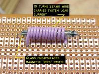
To protect the motor from overload current, Reed switch may be a very simple and low cost solution. Put several turns on a reed switch and then let pass the motor phase current through the winding. At over current, reed switch contact will close and will give trip signal. Make three of them and put the contacts in parallel. To calculate number of winding turns, first you need to find the operating amp-turn of the reed switch experimentally. But the problem of this method is, operator can not adjust the trip current level depending on different size motors. See below the picture of a reed switch with external winding.

 
  • Like
Reactions: abc_de

    abc_de

    Points: 2
    Helpful Answer Positive Rating
i will try to implement hall effect sensor based current sense circuit. i think its easy and wide current sense also require less external components
 

Hi

You should start practical with hall sensor.

1. Use a load resistance at output ( ACS758 sensor datasheet says that use 4.7k resistance minimum)
2. Use a series resistance after load resistance at output
3. ACS758 sensor has internal low pass filter at output however use a external low pass filter at nearest of output.
 
  • Like
Reactions: abc_de

    abc_de

    Points: 2
    Helpful Answer Positive Rating
When you will see ACS758 block diagram will found that sensor d'not have output impedance resistance. The output impedance determines the load that the circuit can drive and the output level delivered to the next stage.
I will suggest to you 1KΩ resistance or you can change it with your application requirement
 

Status
Not open for further replies.

Similar threads

Part and Inventory Search

Welcome to EDABoard.com

Sponsor

Back
Top