Continue to Site

Welcome to EDAboard.com

Welcome to our site! EDAboard.com is an international Electronics Discussion Forum focused on EDA software, circuits, schematics, books, theory, papers, asic, pld, 8051, DSP, Network, RF, Analog Design, PCB, Service Manuals... and a whole lot more! To participate you need to register. Registration is free. Click here to register now.

[SOLVED] LTSpice, curious simulation problems

Status
Not open for further replies.

DanyR

Member level 3
Joined
Aug 23, 2015
Messages
67
Helped
6
Reputation
12
Reaction score
6
Trophy points
8
Location
Nieuwpoort, Belgium
Activity points
677
LTSpice IV, curious simulation problems

Hi, I encountered some curious simulation problem when simuating this circuit:
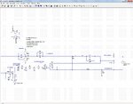
Capture18-12-2015-14.44.15.jpg
View attachment Inverter_6_stability.txt

Plot file: View attachment Inverter_6_stability.plt.txt

The error during simulation is (almost always) something like this:
Capture18-12-2015-14.44.24.jpgwhile there is nothing wrong with the nodes named,and also the named nodes or op-amps can differ after I changed something completely unrelated to the circuit.
Also sometimes the error "... step too small" occurs.

Anyone any suggestions?
Thanks in advance!
 

I have run a simulation with the schematic file you provided. However, instead of using a txt file for LM324 I have used LM324 model file in the following link:

http://ltwiki.org/?title=Components_Library_and_Circuits

Simulation did not give an error, it runs fine. However, I have run it with the default settings. If you changed any parameter like "absolute tolerance / abstol" or "relative tolerance / reltol" to an inappropriate value , it may give an error. One other issue may be about the solvers. I have chosen "normal" solver and "modified trap" integration method. "Gear"/"Alternate" combination may be faster but can cause numerical instability in some cases.
 
  • Like
Reactions: DanyR

    DanyR

    Points: 2
    Helpful Answer Positive Rating
* Guidelines for using op amps state that an input should not be exposed to a voltage outside the supply rails.

* Where exactly is the upper end of resistor 'RLoad'? The zigzag touches the wire coming from the left. It looks odd on a schematic. A reader starts to wonder if it is a proper connection.

* The simulation apparently stops after 11 iterations. See if you can set it to stop after 10 iterations (or 10 timesteps). Then examine volt readings, scope traces, etc.

error "... step too small"

This suggests a timestep error. Try changing it to a longer value.
 
  • Like
Reactions: DanyR

    DanyR

    Points: 2
    Helpful Answer Positive Rating
I have run a simulation with the schematic file you provided. However, instead of using a txt file for LM324 I have used LM324 model file in the following link: http://ltwiki.org/?title=Components_Library_and_Circuits
Simulation did not give an error, it runs fine. However, I have run it with the default settings. If you changed any parameter like "absolute tolerance / abstol" or "relative tolerance / reltol" to an inappropriate value , it may give an error. One other issue may be about the solvers. I have chosen "normal" solver and "modified trap" integration method. "Gear"/"Alternate" combination may be faster but can cause numerical instability in some cases.
Thanks kpc, using the LM324 model you provided solved the problem. Thanks also for the suggestions for the SPICE settings. They help a lot, I am a beginner in using LTSPICE.:-?

- - - Updated - - -

Hi Brad, Thanks for the reply.

* Guidelines for using op amps state that an input should not be exposed to a voltage outside the supply rails.
As fat as I know this is not the case in the circuit diagram I provided (At least I do not see where).

* Where exactly is the upper end of resistor 'RLoad'? The zigzag touches the wire coming from the left. It looks odd on a schematic. A reader starts to wonder if it is a proper connection.
Yes, it seems a bit odd, but the connection was Ok (no "loose" connection was shown, and after "dragging" the RLoad this is clearly shown. But, you are right, the drawing was sloppy (and not onbly there): it was a simplified version of a bigger circuit diagram.

* The simulation apparently stops after 11 iterations. See if you can set it to stop after 10 iterations (or 10 timesteps). Then examine volt readings, scope traces, etc.
How can I stop it after a fixed number of iterations?

This suggests a timestep error. Try changing it to a longer value.
Hoe can I change it to a longer value?

In the mean time: apparently I was using a model of the LM324 that was the cause of the problem, see provious posts.
 

Bad news: also the alternative LM324 (see link to it from kpc a few posts back) is not the solution. The simulation now works on the circuit diagram in the first post but again the same type of errors occur on several of my circuits now that had a correct simulation previously.

But the good news now: using the "UniversalOpamp2" from LTSpice, setup "level.2", gives a good simulation (no errors, no blocking) on all my circuit diagrams.
 

How can I stop it after a fixed number of iterations?

Click Simulate menu. Select Edit Simulation Cmd.
Click Transient tab.
It has options such as stop time, time ot start saving data. Or maybe it will help to try 'Skip Initial operating point solution'.

Hoe can I change it to a longer value?

I'm looking through all the LTSpice IV menus. There is 'maximum timestep' under the Transient tab (as mentioned). The program may not require us to input a timestep.

The program has a Control Panel. Look at the 'Hacks!' tab. See if you want to try any of the convergence hacks.
 
  • Like
Reactions: DanyR

    DanyR

    Points: 2
    Helpful Answer Positive Rating
Hi BradtheRad, thanks for your reply.

Click Simulate menu. Select Edit Simulation Cmd.
Click Transient tab.
It has options such as stop time, time ot start saving data. Or maybe it will help to try 'Skip Initial operating point solution'.
I have tried all of these possibilities in several combinations, without solving the problem.

I'm looking through all the LTSpice IV menus. There is 'maximum timestep' under the Transient tab (as mentioned). The program may not require us to input a timestep.
I also experimented with those... No solution.

The program has a Control Panel. Look at the 'Hacks!' tab. See if you want to try any of the convergence hacks.
I will do so. Thanks! :)
 

The 'singular matrix' error shows up in Falstad's simulator too. Sometimes it is obvious where I made an error, but not always. We need to get experience at trying various tricks to get around these errors, and discover the quirks of the simulator.

Here are more things to try. As we know, they are not faults with real hardware. It's just that we must serve the inflexible simulator algorithm.

* Wherever you put a capacitor, ask yourself whether an RC time constant can be calculated mathematically. You have C4 connected across an AC supply. The simulator cannot determine a time constant. This may be the source of the error. Add a low-ohm resistor inline with C4.

* Add bias resistors to Q1 & Q2. Also low-ohm resistors in their emitter legs.

* U1's non-inverting input is exposed directly to an AC supply. Add an input resistor.
 
  • Like
Reactions: DanyR

    DanyR

    Points: 2
    Helpful Answer Positive Rating
The 'singular matrix' error shows up in Falstad's simulator too. Sometimes it is obvious where I made an error, but not always. We need to get experience at trying various tricks to get around these errors, and discover the quirks of the simulator.

Here are more things to try. As we know, they are not faults with real hardware. It's just that we must serve the inflexible simulator algorithm.

* Wherever you put a capacitor, ask yourself whether an RC time constant can be calculated mathematically. You have C4 connected across an AC supply. The simulator cannot determine a time constant. This may be the source of the error. Add a low-ohm resistor inline with C4.

* Add bias resistors to Q1 & Q2. Also low-ohm resistors in their emitter legs.

* U1's non-inverting input is exposed directly to an AC supply. Add an input resistor.
Hi BradTheRad, according to your suggestions I did a number of experiments. Finally I discovered the source of the problem: the internal series resistor of the supply V3 and V4. I did specify them as being 0.001p (I wanted zero ohms). If I leave out the RSer specification everything works fine, no "singular matrix" problems any more! I do trust LTSpice again! Thanks for the suggestions!
 

Status
Not open for further replies.

Part and Inventory Search

Welcome to EDABoard.com

Sponsor

Back
Top