Continue to Site

Welcome to EDAboard.com

Welcome to our site! EDAboard.com is an international Electronics Discussion Forum focused on EDA software, circuits, schematics, books, theory, papers, asic, pld, 8051, DSP, Network, RF, Analog Design, PCB, Service Manuals... and a whole lot more! To participate you need to register. Registration is free. Click here to register now.

Flyback converter high initial current spike at turn on

Status
Not open for further replies.

chaitanyab

Member level 3
Joined
Dec 8, 2009
Messages
67
Helped
3
Reputation
6
Reaction score
3
Trophy points
1,288
Location
Pune
Activity points
1,877
Current Spike.png**broken link removed**Hi,

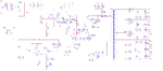
I am facing an issue, my flyback converter at turn on is having a large initial current spike at every PWM more than what the RC filter(1K,300pf) can suppress.

It is causing the PWM to oscillate and the Mosfet is becoming hot.

I have plenty of secondaries but the transformer's interwinding capacitance isn't high.


I don't know, is this normal? Any suggestions to reduce it?

I have R and C parallel combination like PI in error amp feedback, does making it PID with series C will help?


Regards,

Chaitanya
 

Apparently, something in your circuit causes the current peak. Show a schematic.

How are measuring the current? Source shunt?
 

.**broken link removed**

Please find attached schematic. Current shown in previously attached image is measured across the shunt.
 

Attachments

  • FLYB Schematic.png
    FLYB Schematic.png
    107.5 KB · Views: 425
Last edited:

You see a sum of C15, D2 junction capacitance and transformer windings and PCB wiring capacitance. SiCFET is turning on pretty fast, resulting in respective high currents.
 
Hi FvM,

Thanks.
I have measured the caps, C15 is 20pf, Transformer Cp is 22pF, Diode Junction cap is 40pF, I am measuring a current close 3A. A overall capacitor of 100pf and 410V and 37ns SIC fet turn on time it results (I=C*dv/dt) 1.11A which is quite lower than what I am observing.

do you think the snubber cap also should be considered in this calculation?How do we estimate the current?

Regards,

Chaitanya
 

I don't think that there are larger capacitances than those you calculated. The high-side snubber diode must be obviously reverse biased at switching time.

But there might be a problem of shunt inductance + inductive coupling into the sense circuit which makes the current peak appearing larger than it actually is. Measuring the actual current with a small current transformer or rogowski coil would be the best way to check.
 
Hi FvM,

thanks again. I am planning to slow down the SIC fet, even 1A is going to cause the Isense comparator to trip as it has a threshold of 1V. Do you think use of SIC FET was good idea in such high voltage (upto 500V DC input) applications? what you would have use? I have a plenty of bus caps 4 uF, and I have DC input coming to my board, do you think they can cause this quick discharge current and are those required?

Regards,

Chaitanya
 

d8 bzt.. to ground not mosfet source.
 
Your R11*C17 330ns time constant may not attenuate the leading edge spike enough . You can put a 49~50 Ohm series R on the I sense and terminate with 50 Ohms using semi-rigid or good microwave flex coax to accurately measure I/2. I would put an SM coax connector on board.

You may wish to add a soft start to the board until it reaches regulation by changing the current sense gain. The load caps need to charge up and starting surge will be high.
 
Last edited:
I am planning to slow down the SIC fet, even 1A is going to cause the Isense comparator to trip as it has a threshold of 1V.

It would be interesting to see the current peaks before and behind the 330 ns filter with higher time resolution. I agree with SunnySkyguide that a larger time constant (e.g. up to 1 µs) can possibly work. The question is if the current peak still matters after being low pass filtered, in other words it's As area can't be ignored.

Do you think use of SIC FET was good idea in such high voltage (upto 500V DC input) applications? what you would have use?
I see that there are very few MOSFET in the 1200V class, e.g. ST has some. But the lastest when you need to slow down the SiC switching speed you should consider to return to regular Si MOSFET.

I have a plenty of bus caps 4 uF, and I have DC input coming to my board, do you think they can cause this quick discharge current and are those required?
I prefer to consider good DC bus bypassing as a feature rather than a problem.
 
SunnySkyGuy has it right, and FvM...you just keep making the CS pin filter heavier until your spike goes......what is the spike like on the cs pin itself.
Because you have so many secondaries, your turn-on spike will indeed be high...because all those secondary schottkys have a capacitance and the suddent build up of voltage across these schottkys results in the sudden spikes of current going thru the txfmr and thru your sense resistor....if you want you can use eg lt1246 which has a dead-time where it ignores the turn-on spike.'''its officially called "Leading Edge Blanking" (LEB).

obviously the RCD diode has to be ultra fast....eg trr = 50ns or less.
 
.
Hello Everyone,

Thanks I am extremely happy with the responses. Somehow I didn't get the email notification that I normally get when there is a reply.
I have reduced the speed and removed the C15 and it has reduced the pulse current but it is still high.
One thing I noticed if this current is stopped reaching the PWM IC then it works but the FET is still getting hot.

I found this link particularly interesting https://www.edn.com/design/analog/4333114/Circuit-provides-leading-edge-blanking

Hi FvM, Do you recommend any particular Si FET, I am worried about need of an external Totempole for such a FET.

Hi SunnySkyGuy, I am having a softstart which in fact I need to disable then only it was starting R12,C21, probably low R value loading the Vref.


Hi Treez, I am struggling to replace the snubber diode with 1000V and low capacitance and highspeed, probably a shottkey, do you recommend any special series? For the secondary Will the SIC Diode with lower junction caps will help? At this point obviously I am not comfortable with SIC still might be worth a try, what do you think? I will definitely study LT1246.

Thanks,

Chaitanya
 

Your diode D2 looks like a general-purpose 1kV rectifier diode. I would change that to a much faster diode, something like a MUR490E or MUR4100E. I am sure that may cause you problems.

- - - Updated - - -

Here is an example of a 80W flyback running at 50kHz where you can see the difference in current spikes when trying to use a slow snubber diode. It looks very similar to what you are seeing with your design.

- - - Updated - - -

The MUR2100E is another possibility.
 

Attachments

  • snubber.png
    snubber.png
    22.8 KB · Views: 245
Last edited:
Status
Not open for further replies.

Part and Inventory Search

Welcome to EDABoard.com

Sponsor

Back
Top