Continue to Site

Welcome to EDAboard.com

Welcome to our site! EDAboard.com is an international Electronics Discussion Forum focused on EDA software, circuits, schematics, books, theory, papers, asic, pld, 8051, DSP, Network, RF, Analog Design, PCB, Service Manuals... and a whole lot more! To participate you need to register. Registration is free. Click here to register now.

What is the role of interpolation filter in a digital audio amplifier?

Status
Not open for further replies.

CHL

Member level 3
Joined
Jan 20, 2015
Messages
60
Helped
2
Reputation
4
Reaction score
2
Trophy points
8
Activity points
550
Hello

I wonder why we need an interpolation filter in a digital audio amplifier.

Oversampling can be performed through a digital delta-sigma modulator, so PCM signals from a DSP can be oversampled after the modulator.

Why do we need the interpolation filter in front of the delta-sigma modulator?
 

A time discrete signal f1 (e.g. 44 kHz CD-audio) has image frequencies at n*fs+/-f1. They must be suppressed with a low-pass filter of fs/2 cut-off frequency. Without interpolation, the image frequencies are still present in the upsampled signal.
 
  • Like
Reactions: CHL

    CHL

    Points: 2
    Helpful Answer Positive Rating
N bit interpolation filter design for audio amplifiers

Hello

I need to design a digital audio amplifier, but I cannot understand how to design an interpolation filter. (I know what the basic principle of the filter is)

Let's assume that 16 bit PCM signals from a DSP go to the input of the filter.

The PCM signals consist of series 0 and 1, so they should be changed from binary to decimal if we want to know the real value.

It means the filter needs a DAC in front of the filter.

However, there is a DAC after the filter in the audio amplifier block.

If the PCM signal itself goes to the interpolation filter, how can it be upsampled?

Is there a 16 bit register in the filter?

I want to know how to design N bit interpolation filter.
 

Re: N bit interpolation filter design for audio amplifiers

Take the series of 16 bit values at the system input sample rate, interleve with an appropriate number of zero values to get to the output rate then apply a digital lowpass at the output rate with a stop band starting just below half the input rate, job done (This is typically done IN the DSP chip, you would output at whatever rate is appropriate to the following stage).

Now there are obvious ways to optimise this, for example with FIR filters you don't actually need to calculate the convolution on all those zeros, instead you can have multiple sets of filter coefficients.

Regards, Dan.

Hi

Does the interpolation filter need a clock to check the 16bit PCM?
 

PCM input to a sigma-delta modulator in a digital audio amplifier

Hello

I have a question about multibit input to a sigma-delta modulator.

In digital audio amp circuits, normally 16bit PCM signal is provided to the SD modulator.

However, I cannot find papers explaining how the multibit input is inserted to the modulator.

Is it parallel? or series?

If it is series, do we need a clock signal for the communication?

Also, in both cases, should we change the binary signal to decimal signal using a DAC before the SD modulator?

Thanks
 

Re: PCM input to a sigma-delta modulator in a digital audio amplifier

Which SD modulator are you talking about? A commercial audio DAC or a modulator you are going to design yourself from the scratch?

The SD modulator itself needs a clock, both for the output modulator and any digital signal processing performed in front of it. The digital audio data arrives with a defined sample rate, quite obviously the interface has to be designed to fit the rate, either if it's serial or parallel. All recent audio DACs are using a serial protocol, depending on the protocol, either the audio source or the DAC act as a master which provides bit and frame clock.

The involved digital signal processing can be described as a rate conversion, the multibit signal is converted to a single bit signal of a multiple sampling rate.

There's no use of decimal data formats in the digital signal processing.
 

There are filterless class-D audio amplifier ICs available. The switching frequency is suppressed in the modulation.
 

Re: PCM input to a sigma-delta modulator in a digital audio amplifier

I'm trying to design IC.
I cannot understand how 16bit PCM signal (binary) can be converted to PDM.
To convert the signal to PDM, we need to know the PCM voltage level, eg 0.5V or 1V.
Serial binary itself cannot be converted to PDM signals.
Is a DAC needed to convert PCM to voltage level in front of a SD modulator?
 

If you consider a basic (single bit) SD-DAC design, the conversion of digital bitstream to analog voltage takes place in the output stage.
 

    V

    Points: 2
    Helpful Answer Positive Rating
Can you explain how serial bits can be 1bit PDM signals?
For example, if the PCM input is '1 0 1 0' and the binary codes themselves are the input signal, I think the SD modulator output should be '1111 0000 1111 0000'(when OSR=4). This is a wrong result.
The right result should be like this, '1111 1111 1100 0000' (the density shows 10/16)
I don't understand how multibit signals are converted to 1-bit PDM signals.
 

I don't understand to which coding "PCM input is '1 0 1 0'" refers. I also don't see 4-bit coded PCM involved in audio systems.

In digital audio, we have binary coded data, e.g. 16-bit in standard CD format, 24 or 32 bit in other standards. These data stream can be transmitted parallel or serial, most audio DACs get their input serially. But the 16 data bit form a frame, each bit has a different weight. So they are surely not simply copied to an output bitstream. Instead they are send to an interpolation filter which increases the sampling rate to the intended output rate. Then sent to the SD modulator that (in the simplest case of a 1-bit DAC) forms the one-bit output bitstream.

My personal literature suggestion in this regard Delta-Sigma Data Converters - Theory, Design and Simulation by Norsworthy, Schreier, Temes.

Now I understand how it works.

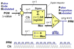
PPM.gif
http://www.thinkcreate.org/wp-content/uploads/2011/03/PPM.gif

The image makes it clear.

Thank you for your helps!
 
  • Like
Reactions: FvM

    FvM

    Points: 2
    Helpful Answer Positive Rating
Status
Not open for further replies.

Part and Inventory Search

Welcome to EDABoard.com

Sponsor

Back
Top