Continue to Site

Welcome to EDAboard.com

Welcome to our site! EDAboard.com is an international Electronics Discussion Forum focused on EDA software, circuits, schematics, books, theory, papers, asic, pld, 8051, DSP, Network, RF, Analog Design, PCB, Service Manuals... and a whole lot more! To participate you need to register. Registration is free. Click here to register now.

[SOLVED] need help in Power Control PWM in PIC18F4431

Status
Not open for further replies.

abc_de

Full Member level 5
Joined
Jan 9, 2014
Messages
243
Helped
11
Reputation
22
Reaction score
11
Trophy points
1,298
Location
Ludhiana ਪੰਜਾਬ
Activity points
2,939
hello
i am working on pwer control pwm of pic18f4431 and try get variable duty cycle of PWM
at 20 khz on all pwm pins. all pwm channels are configure in complementary mde.
i am facing problem while changing duty cycle, frequency of pwm signal is perfect. please help me:???::???:

here is my code

Code:
#include"p18f4431.h"


#pragma config OSC 		= IRCIO	// 	INTERNAL OSCILLATOR IS ON
#pragma config DEBUG	= OFF   // 	DEBUGGER IS OFF
#pragma config LVP  	= OFF   //	Low-voltage ICSP disabled  
#pragma config PWRTEN 	= OFF	// 	PWRTEN Disabled 
#pragma config WDTEN 	= OFF	//	WDT disabled    
#pragma config MCLRE	= ON	//	MCLR Pin Enabled 
#pragma config BOREN 	= OFF	//	Brown-out Reset disabled 

#pragma config PWMPIN	= OFF	//	PWM outputs disabled upon Reset (default) 
#pragma config LPOL 	= HIGH	//	PWM0, 2, 4 and 6 are active-high 
#pragma config HPOL 	= HIGH	//	PWM1, 3, 5 and 7 are active-high

#pragma config PWM4MX 	= RB5	//	PWM4 output is multiplexed with RB5 
#pragma config FLTAMX 	= RC1	//	FLTA input is multiplexed with RC1 

#pragma config SSPMX 	= RC7	//	SCK/SCL clocks and SDA/SDI data are multiplexed with RC5 and RC4, respectively. SDO output is multiplexed with RC7.
#pragma config EXCLKMX 	= RC3	//	TMR0/T5CKI external clock input is multiplexed with RC3 

void pwm_int(void);


void pwm_int(void)
{
PORTB=0x00;
TRISBbits.TRISB0=0; //	PWM0
TRISBbits.TRISB1=0; //	PWM1

TRISBbits.TRISB2=0; //	PWM2
TRISBbits.TRISB3=0; //	PWM3

TRISBbits.TRISB5=0; //	PWM4
TRISBbits.TRISB4=0; //	PWM5

TRISDbits.TRISD6=0; //	PWM6
TRISDbits.TRISD7=0; //	PWM7

// interrupt control register 
INTCON=0XC0; 		// enabl;e globle and peripheral interrupts
IPR3bits.PTIP=1;	// enable timer 1 interrupt priorty high 
PIE3bits.PTIE=1;	// enable timer 1 
PIR3bits.PTIF=0;	// disable timer 1 flag  


// PWM Special Event Compare Registers
SEVTCMPL=0X00;
SEVTCMPH=0X00;


//DEAD TIME CONTROL REGISTER
DTCON=8; 			// 	dead time arround 2 usec


//FAULT CONFIGURATION REGISTER
FLTCONFIG=0X00; 	// 	disable fault detection feature


//OUTPUT OVERRIDE CONTROL REGISTER
OVDCOND=0XFF;		//	Output on PWM I/O pin is controlled by the value in the Duty Cycle register and the PWM time base.


// OUTPUT STATE REGISTER
OVDCONS=0X00;		//	Output on PWM I/O pin is INACTIVE when the corresponding PWM output override bit is cleared.

// pwm timer register 
PTMRL=0X00;			//	PWM Time Base (lower 8 bits)
PTMRH=0X00;			//	PWM Time Base (upper 4 bits)


// PWM TIMER CONTROL REGISTER 0
PTCON0=0X00;		//	1:1 Postscale,Fosc/4 (1:1 prescale),Free Running mode

// PWM TIMER CONTROL REGISTER 1
PTCON1=0X80; 		//	PWM time base is ON


// PWM CONTROL REGISTER 0
PWMCON0=0X50; 		//	All PWM I/O pins enabled for PWM output, complementary mode
// PWM CONTROL REGISTER 1
PWMCON1=0X01;  

//PWM Time Base Period Registers
PTPERL=124;			//	PWM Time Base Period (lower 8 bits)
PTPERH0;			//	PWM Time Base Period (upper 4 bits)


//PWM Duty cycle registers 
PDC0L=60;			//	PWM Duty Cycle #0L register (Lower 8 bits)
PDC0H=0; 			//	PWM Duty Cycle #0H register (Upper 6 bits)

PDC1L=60;			//	PWM Duty Cycle #1L register (Lower 8 bits)
PDC1H=0;			//	PWM Duty Cycle #2H register (Upper 6 bits)

PDC2L=60;			//	PWM Duty Cycle #2L register (Lower 8 bits)
PDC2H=0;			//	PWM Duty Cycle #2H register (Upper 6 bits)

PDC3L=60;			//	PWM Duty Cycle #3L register (Lower 8 bits)
PDC3H=0;			//	PWM Duty Cycle #3H register (Upper 6 bits)

ADCON0=0x00;// ADC MODULE IS DISABLE


}


void main(void)
{
OSCCON=0X72;   // internal osc. at 8 mhz 
ANSEL0=ANSEL1=0X00;  // disable analog pins 
pwm_int();
while(1);


}
 
Last edited:

Hi,

I suppose the PWM duty counter register used for p18f4431 need to be analysed properly.

The Period register (PTPERL, PTPERH) are 12 bit(8bit+4bit). Hence the Duty register (PDCnL,PDCnH) should also be 12 bit as it would be compared against the period register. But in the data sheet it is mentioned as 14 Bit (Datasheet for PIC18F2331/2431/4331/4431-Pg 197/396).

However the duty register has the 0th and 1st bit as the Q Clock value, so the duty counter must be assigned to the 2nd~7th bit (in PDCnL) and 0th~6th bit (in PDCnH). i.e effectively 12 Bits. The same as been explained in the below attached figure.

DutyRegister.jpg.

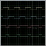
The working code for the Power Control PWM module for PIC18F4431 has been mentioned below. This has been tested with skeleton circuit for PIC18F4431 chip on simulation softaware and the duty cycles measured through simulation DSO.

PIC18F4431_Schematic.jpg

DSO_Image.jpg

Code:
/* 
 * File:   Main.c
 * Author: ADITYA RAJ NAYAK
 * 
 * Created on 11 January, 2015, 7:07 PM
 */

#include    <stdio.h>
#include    <stdlib.h>
#include    "p18f4431.h"

#define     BIT_SHIFT_0         0x00
#define     BIT_SHIFT_1         0x01
#define     BIT_SHIFT_2         0x02
#define     BIT_SHIFT_3         0x03
#define     BIT_SHIFT_4         0x04
#define     BIT_SHIFT_5         0x05
#define     BIT_SHIFT_6         0x06
#define     BIT_SHIFT_7         0x07
#define     BIT_SHIFT_8         0x08

#define     MINDUTYPERCENT      0x00            //0%
#define     MAXDUTYPERCENT      0x64            //100%
#define     MINDUTYCNT          0x0000          //0
#define     MAXDUTYCNT          0x0FFF          //For 12 bit Counter

#define     CHANNEL0_PAIR       0x00            //PWM 0, 1 Pair
#define     CHANNEL1_PAIR       0x01            //PWM 2, 3 Pair
#define     CHANNEL2_PAIR       0x02            //PWM 4, 5 Pair
#define     CHANNEL3_PAIR       0x03            //PWM 6, 7 Pair

#define     FREQUENCY_20HZ      20              //20 Hz
#define     FREQUENCY_1KHZ      1000            //1 KHz

#pragma config OSC	= IRCIO                 //INTERNAL OSCILLATOR IS ON
#pragma config DEBUG	= OFF                   //DEBUGGER IS OFF
#pragma config LVP  	= OFF                   //Low-voltage ICSP disabled
#pragma config PWRTEN 	= OFF                   //PWRTEN Disabled
#pragma config WDTEN 	= OFF                   //WDT disabled
#pragma config MCLRE	= ON                    //MCLR Pin Enabled
#pragma config BOREN 	= OFF                   //Brown-out Reset disabled

#pragma config PWMPIN	= OFF                   //PWM outputs disabled upon Reset (default)
#pragma config LPOL 	= HIGH                  //PWM0, 2, 4 and 6 are active-high
#pragma config HPOL 	= HIGH                  //PWM1, 3, 5 and 7 are active-high

#pragma config PWM4MX 	= RB5                   //PWM4 output is multiplexed with RB5
#pragma config FLTAMX 	= RC1                   //FLTA input is multiplexed with RC1

#pragma config SSPMX 	= RC7                   //SCK/SCL clocks and SDA/SDI data are multiplexed with RC5 and RC4, respectively. SDO output is multiplexed with RC7.
#pragma config EXCLKMX 	= RC3                   //TMR0/T5CKI external clock input is multiplexed with RC3

typedef struct PWMProperty
{
    unsigned int PeriodCnt;                     //Conunt for Period max 12 Bit
    unsigned int DutyCycleCnt;                  //Conunt for Duty max 12 Bit
    unsigned int DutyCyclePercent;              //Vary between 0~100%
}pwmproperty;
pwmproperty pwmproperty1;                       //To store PWM propoerties

void pwm_int(void);
void pwm_init_test(void);
int LIMIT(int value, int min, int max);
void setPWMPeriod(pwmproperty *pwmsignal,unsigned int FreqHz);
void setDutyCycle(unsigned char channelno ,pwmproperty *pwmsignal, unsigned int percent);

int LIMIT(int value, int min, int max)
{
    if(value > max)
    {
        value = max;
    }
    else if(value < min)
    {
        value = min;
    }
    return (value);
}

void main(void) {
  int i =0;
  OSCCON=0X72;              // internal osc. at 8 mhz
  ANSEL0=ANSEL1=0X00;       // disable analog pins
  pwm_init_test();
  while(1)
  {
  //Infinite Loop to go on and on and on and on
  }
}
void pwm_init_test(void)
{
    PORTB               =0x00;
    TRISBbits.TRISB0    =0x00; //	PWM0
    TRISBbits.TRISB1    =0x00; //	PWM1

    TRISBbits.TRISB2    =0x00; //	PWM2
    TRISBbits.TRISB3    =0x00; //	PWM3

    TRISBbits.TRISB5    =0x00; //	PWM4
    TRISBbits.TRISB4    =0x00; //	PWM5

    TRISDbits.TRISD6    =0x00; //	PWM6
    TRISDbits.TRISD7    =0x00; //	PWM7

    PTMRL   =0X00;			//	PWM Time Base (lower 8 bits)
    PTMRH   =0X00;			//	PWM Time Base (upper 4 bits)

    PTPERL  =0X00;			//	PWM Time Base Period (lower 8 bits)
    PTPERH  =0X00;			//	PWM Time Base Period (upper 4 bits)

    PDC0L   =0X00;			//	PWM Duty Cycle #0L register (Lower 8 bits)
    PDC0H   =0X00; 			//	PWM Duty Cycle #0H register (Upper 6 bits)

    PDC1L   =0X00;			//	PWM Duty Cycle #1L register (Lower 8 bits)
    PDC1H   =0X00;			//	PWM Duty Cycle #2H register (Upper 6 bits)

    PDC2L   =0X00;			//	PWM Duty Cycle #2L register (Lower 8 bits)
    PDC2H   =0X00;			//	PWM Duty Cycle #2H register (Upper 6 bits)

    PDC3L   =0X00;			//	PWM Duty Cycle #3L register (Lower 8 bits)
    PDC3H   =0X00;			//	PWM Duty Cycle #3H register (Upper 6 bits)
////////////////////////////////////////////////////////////////////////////////
    /*PTCON0: PWM TIMER CONTROL REGISTER 0*/
    /* bit 7-4 PTOPS3:PTOPS0: PWM Time Base Output Postscale Select bits
        X0000 =1:1 Postscale
        0001 =1:2 Postscale
        .
        .
        1111 =1:16 Postscale
     */
    /* bit 3-2 PTCKPS1:PTCKPS0: PWM Time Base Input Clock Prescale Select bits
        X00 =PWM time base input clock is Fosc/4 (1:1 prescale)
        01 =PWM time base input clock is Fosc/16 (1:4 prescale)
        10 =PWM time base input clock is Fosc/64 (1:16 prescale)
        11 =PWM time base input clock is Fosc/256 (1:64 prescale)
    */
    /*bit 1-0 PTMOD1:PTMOD0: PWM Time Base Mode Select bits
        11 =PWM time base operates in a Continuous Up/Down mode with interrupts for double PWM        updates.
        10 =PWM time base operates in a Continuous Up/Down Counting mode.
        01 =PWM time base configured for Single-shot mode.
        X00 =PWM time base operates in a Free Running mode.
     */

    PTCON0  = 0x00
            |(0x00     << BIT_SHIFT_4)
            |(0x00     << BIT_SHIFT_2)
            |(0x00);
////////////////////////////////////////////////////////////////////////////////
    /*PTCON1: PWM TIMER CONTROL REGISTER 1*/
    /*bit 7 PTEN: PWM Time Base Timer Enable bit
        1 = PWM time base is ON
        X0 = PWM time base is OFF
     */
    /*bit 6 PTDIR: PWM Time Base Count Direction Status bit
        1 = PWM time base counts down.
        X0 = PWM time base counts up.
     */
    /*bit 5-0 Unimplemented: Read as ?0?. */
    PTCON1  = 0x00
            |(0x01     << BIT_SHIFT_7)
            |(0x00     << BIT_SHIFT_6);
////////////////////////////////////////////////////////////////////////////////
    /*PWMCON0: PWM CONTROL REGISTER 0*/
    /*bit 7 Unimplemented: Read as ?0?.*/
    /*bit 6-4 PWMEN2:PWMEN0: PWM Module Enable bits(1)
        111 =All odd PWM I/O pins enabled for PWM output(2).
        110 =PWM1, PWM3 pins enabled for PWM output.
        101 =All PWM I/O pins enabled for PWM output(2) .
        100 =PWM0, PWM1, PWM2, PWM3, PWM4 and PWM5 pins enabled for PWM output.
        011 =PWM0, PWM1, PWM2 and PWM3 I/O pins enabled for PWM output.
        010 =PWM0 and PWM1 pins enabled for PWM output.
        001 =PWM1 pin is enabled for PWM output.
        000 =PWM module disabled. All PWM I/O pins are general purpose I/O.
     */
    /*bit 3-0 PMOD3:PMOD0: PWM Output Pair Mode bits
        For PMOD0:
        1 = PWM I/O pin pair (PWM0, PWM1) is in the Independent mode.
        0 = PWM I/O pin pair (PWM0, PWM1) is in the Complementary mode.
        For PMOD1:
        1 = PWM I/O pin pair (PWM2, PWM3) is in the Independent mode.
        0 = PWM I/O pin pair (PWM2, PWM3) is in the Complementary mode.
        For PMOD2:
        1 = PWM I/O pin pair (PWM4, PWM5) is in the Independent mode.
        0 = PWM I/O pin pair (PWM4, PWM5) is in the Complementary mode.
        For PMOD3(3):
        1 = PWM I/O pin pair (PWM6, PWM7) is in the Independent mode.
        0 = PWM I/O pin pair (PWM6, PWM7) is in the Complementary mode.
     */
    PWMCON0  = 0x00
            |(0x05     << BIT_SHIFT_4)
            |(0x00);
////////////////////////////////////////////////////////////////////////////////
    /*PWMCON1: PWM CONTROL REGISTER 1
    bit 7-4 SEVOPS3:SEVOPS0: PWM Special Event Trigger Output Postscale Select bits
        0000 =1:1 Postscale
        0001 =1:2 Postscale
        .
        1111 =1:16 Postscale
    bit 3 SEVTDIR: Special Event Trigger Time Base Direction bit
        1 = A special event trigger will occur when the PWM time base is counting downwards.
        0 = A special event trigger will occur when the PWM time base is counting upwards.
    bit 2 Unimplemented: Read as ?0?.
    bit 1 UDIS: PWM Update Disable bit
        1 = Updates from duty cycle and period buffer registers are disabled.
        0 = Updates from duty cycle and period buffer registers are enabled.
    bit 0 OSYNC: PWM Output Override Synchronization bit
        1 = Output overrides via the OVDCON register are synchronized to the the PWM time base.
        0 = Output overrides via the OVDCON register are asynchronous.*/
    PWMCON1  = 0x00
            |(0x00     << BIT_SHIFT_4)
            |(0x00     << BIT_SHIFT_3)
            |(0x00     << BIT_SHIFT_1)
            |(0x01);
////////////////////////////////////////////////////////////////////////////////

    setPWMPeriod(&pwmproperty1,FREQUENCY_1KHZ);
    setDutyCycle(CHANNEL0_PAIR,&pwmproperty1,25);
    setDutyCycle(CHANNEL1_PAIR,&pwmproperty1,50);
    setDutyCycle(CHANNEL2_PAIR,&pwmproperty1,75);
    setDutyCycle(CHANNEL3_PAIR,&pwmproperty1,10);
}

void setPWMPeriod(pwmproperty *pwmsignal,unsigned int FreqHz)
{
    unsigned long    Fosc            = 8000000;         //8 MHz
    unsigned int     ptmrpsreg       = 0x01;            //1:1
    unsigned int     ptperreg        = 0x00;
    unsigned char    ptperregL       = 0x00;
    unsigned char    ptperregH       = 0x00;

    ptperreg = ((Fosc/4)/(ptmrpsreg*FreqHz))-1;
    pwmsignal->PeriodCnt = ptperreg;
    ptperreg = ptperreg&0x0FFF;

    ptperregL   = ptperreg&0x00FF;
    ptperregH   = (ptperreg&0x0F00)>>BIT_SHIFT_8;

    PTPERL = ptperregL;			//	PWM Time Base Period (lower 8 bits)
    PTPERH = ptperregH;			//	PWM Time Base Period (upper 4 bits)
    
}
void setDutyCycle(unsigned char channelno ,pwmproperty *pwmsignal,  unsigned int percent)
{
    unsigned char    dutycntL    = 0x00;
    unsigned char    dutycntH    = 0x00;
    unsigned int     dutycnt     = 0x00;
    unsigned long    period      = 0x00;
    unsigned int     temp        = 0x00;

    LIMIT(percent, MINDUTYPERCENT, MAXDUTYPERCENT);
    pwmsignal->DutyCyclePercent  = percent;
    period = pwmsignal->PeriodCnt;
    pwmsignal->DutyCycleCnt      = (percent*period/100);
    LIMIT(pwmsignal->DutyCycleCnt, MINDUTYCNT, MAXDUTYCNT);
    
    switch(channelno)
    {
        case CHANNEL0_PAIR:
            dutycnt     = pwmsignal->DutyCycleCnt << BIT_SHIFT_2;
            dutycntL    = dutycnt & 0x00FF;
            dutycntH    = (dutycnt & 0x3F00)>>BIT_SHIFT_8;
            PDC0L       = dutycntL;
            PDC0H       = dutycntH;
            break;
        case CHANNEL1_PAIR:
            dutycnt     = pwmsignal->DutyCycleCnt << BIT_SHIFT_2;
            dutycntL    = dutycnt & 0x00FF;
            dutycntH    = (dutycnt & 0x3F00)>>BIT_SHIFT_8;
            PDC1L       = dutycntL;
            PDC1H       = dutycntH;
            break;
        case CHANNEL2_PAIR:
            dutycnt     = pwmsignal->DutyCycleCnt << BIT_SHIFT_2;
            dutycntL    = dutycnt & 0x00FF;
            dutycntH    = (dutycnt & 0x3F00)>>BIT_SHIFT_8;
            PDC2L       = dutycntL;
            PDC2H       = dutycntH;
            break;
        case CHANNEL3_PAIR:
            dutycnt     = pwmsignal->DutyCycleCnt << BIT_SHIFT_2;
            dutycntL    = dutycnt & 0x00FF;
            dutycntH    = (dutycnt & 0x3F00)>>BIT_SHIFT_8;
            PDC3L       = dutycntL;
            PDC3H       = dutycntH;
            break;
        default:

            break;
    }
}

Hope this solves the issue.
 
Thank u alot problem has been solved

Code:
/* 
 * File:   Main.c
 * Author: ADITYA RAJ NAYAK
 * 
 * Created on 11 January, 2015, 7:07 PM
 */

#include    <stdio.h>
#include    <stdlib.h>
#include    "p18f4431.h"

#define     BIT_SHIFT_0         0x00
#define     BIT_SHIFT_1         0x01
#define     BIT_SHIFT_2         0x02
#define     BIT_SHIFT_3         0x03
#define     BIT_SHIFT_4         0x04
#define     BIT_SHIFT_5         0x05
#define     BIT_SHIFT_6         0x06
#define     BIT_SHIFT_7         0x07
#define     BIT_SHIFT_8         0x08

#define     MINDUTYPERCENT      0x00            //0%
#define     MAXDUTYPERCENT      0x64            //100%
#define     MINDUTYCNT          0x0000          //0
#define     MAXDUTYCNT          0x0FFF          //For 12 bit Counter

#define     CHANNEL0_PAIR       0x00            //PWM 0, 1 Pair
#define     CHANNEL1_PAIR       0x01            //PWM 2, 3 Pair
#define     CHANNEL2_PAIR       0x02            //PWM 4, 5 Pair
#define     CHANNEL3_PAIR       0x03            //PWM 6, 7 Pair

#define     FREQUENCY_20HZ      20              //20 Hz
#define     FREQUENCY_1KHZ      1000            //1 KHz

#pragma config OSC	= IRCIO                 //INTERNAL OSCILLATOR IS ON
#pragma config DEBUG	= OFF                   //DEBUGGER IS OFF
#pragma config LVP  	= OFF                   //Low-voltage ICSP disabled
#pragma config PWRTEN 	= OFF                   //PWRTEN Disabled
#pragma config WDTEN 	= OFF                   //WDT disabled
#pragma config MCLRE	= ON                    //MCLR Pin Enabled
#pragma config BOREN 	= OFF                   //Brown-out Reset disabled

#pragma config PWMPIN	= OFF                   //PWM outputs disabled upon Reset (default)
#pragma config LPOL 	= HIGH                  //PWM0, 2, 4 and 6 are active-high
#pragma config HPOL 	= HIGH                  //PWM1, 3, 5 and 7 are active-high

#pragma config PWM4MX 	= RB5                   //PWM4 output is multiplexed with RB5
#pragma config FLTAMX 	= RC1                   //FLTA input is multiplexed with RC1

#pragma config SSPMX 	= RC7                   //SCK/SCL clocks and SDA/SDI data are multiplexed with RC5 and RC4, respectively. SDO output is multiplexed with RC7.
#pragma config EXCLKMX 	= RC3                   //TMR0/T5CKI external clock input is multiplexed with RC3

typedef struct PWMProperty
{
    unsigned int PeriodCnt;                     //Conunt for Period max 12 Bit
    unsigned int DutyCycleCnt;                  //Conunt for Duty max 12 Bit
    unsigned int DutyCyclePercent;              //Vary between 0~100%
}pwmproperty;
pwmproperty pwmproperty1;                       //To store PWM propoerties

void pwm_int(void);
void pwm_init_test(void);
int LIMIT(int value, int min, int max);
void setPWMPeriod(pwmproperty *pwmsignal,unsigned int FreqHz);
void setDutyCycle(unsigned char channelno ,pwmproperty *pwmsignal, unsigned int percent);

int LIMIT(int value, int min, int max)
{
    if(value > max)
    {
        value = max;
    }
    else if(value < min)
    {
        value = min;
    }
    return (value);
}

void main(void) {
  int i =0;
  OSCCON=0X72;              // internal osc. at 8 mhz
  ANSEL0=ANSEL1=0X00;       // disable analog pins
  pwm_init_test();
  while(1)
  {
  //Infinite Loop to go on and on and on and on
  }
}
void pwm_init_test(void)
{
    PORTB               =0x00;
    TRISBbits.TRISB0    =0x00; //	PWM0
    TRISBbits.TRISB1    =0x00; //	PWM1

    TRISBbits.TRISB2    =0x00; //	PWM2
    TRISBbits.TRISB3    =0x00; //	PWM3

    TRISBbits.TRISB5    =0x00; //	PWM4
    TRISBbits.TRISB4    =0x00; //	PWM5

    TRISDbits.TRISD6    =0x00; //	PWM6
    TRISDbits.TRISD7    =0x00; //	PWM7

    PTMRL   =0X00;			//	PWM Time Base (lower 8 bits)
    PTMRH   =0X00;			//	PWM Time Base (upper 4 bits)

    PTPERL  =0X00;			//	PWM Time Base Period (lower 8 bits)
    PTPERH  =0X00;			//	PWM Time Base Period (upper 4 bits)

    PDC0L   =0X00;			//	PWM Duty Cycle #0L register (Lower 8 bits)
    PDC0H   =0X00; 			//	PWM Duty Cycle #0H register (Upper 6 bits)

    PDC1L   =0X00;			//	PWM Duty Cycle #1L register (Lower 8 bits)
    PDC1H   =0X00;			//	PWM Duty Cycle #2H register (Upper 6 bits)

    PDC2L   =0X00;			//	PWM Duty Cycle #2L register (Lower 8 bits)
    PDC2H   =0X00;			//	PWM Duty Cycle #2H register (Upper 6 bits)

    PDC3L   =0X00;			//	PWM Duty Cycle #3L register (Lower 8 bits)
    PDC3H   =0X00;			//	PWM Duty Cycle #3H register (Upper 6 bits)
////////////////////////////////////////////////////////////////////////////////
    /*PTCON0: PWM TIMER CONTROL REGISTER 0*/
    /* bit 7-4 PTOPS3:PTOPS0: PWM Time Base Output Postscale Select bits
        X0000 =1:1 Postscale
        0001 =1:2 Postscale
        .
        .
        1111 =1:16 Postscale
     */
    /* bit 3-2 PTCKPS1:PTCKPS0: PWM Time Base Input Clock Prescale Select bits
        X00 =PWM time base input clock is Fosc/4 (1:1 prescale)
        01 =PWM time base input clock is Fosc/16 (1:4 prescale)
        10 =PWM time base input clock is Fosc/64 (1:16 prescale)
        11 =PWM time base input clock is Fosc/256 (1:64 prescale)
    */
    /*bit 1-0 PTMOD1:PTMOD0: PWM Time Base Mode Select bits
        11 =PWM time base operates in a Continuous Up/Down mode with interrupts for double PWM        updates.
        10 =PWM time base operates in a Continuous Up/Down Counting mode.
        01 =PWM time base configured for Single-shot mode.
        X00 =PWM time base operates in a Free Running mode.
     */

    PTCON0  = 0x00
            |(0x00     << BIT_SHIFT_4)
            |(0x00     << BIT_SHIFT_2)
            |(0x00);
////////////////////////////////////////////////////////////////////////////////
    /*PTCON1: PWM TIMER CONTROL REGISTER 1*/
    /*bit 7 PTEN: PWM Time Base Timer Enable bit
        1 = PWM time base is ON
        X0 = PWM time base is OFF
     */
    /*bit 6 PTDIR: PWM Time Base Count Direction Status bit
        1 = PWM time base counts down.
        X0 = PWM time base counts up.
     */
    /*bit 5-0 Unimplemented: Read as ?0?. */
    PTCON1  = 0x00
            |(0x01     << BIT_SHIFT_7)
            |(0x00     << BIT_SHIFT_6);
////////////////////////////////////////////////////////////////////////////////
    /*PWMCON0: PWM CONTROL REGISTER 0*/
    /*bit 7 Unimplemented: Read as ?0?.*/
    /*bit 6-4 PWMEN2:PWMEN0: PWM Module Enable bits(1)
        111 =All odd PWM I/O pins enabled for PWM output(2).
        110 =PWM1, PWM3 pins enabled for PWM output.
        101 =All PWM I/O pins enabled for PWM output(2) .
        100 =PWM0, PWM1, PWM2, PWM3, PWM4 and PWM5 pins enabled for PWM output.
        011 =PWM0, PWM1, PWM2 and PWM3 I/O pins enabled for PWM output.
        010 =PWM0 and PWM1 pins enabled for PWM output.
        001 =PWM1 pin is enabled for PWM output.
        000 =PWM module disabled. All PWM I/O pins are general purpose I/O.
     */
    /*bit 3-0 PMOD3:PMOD0: PWM Output Pair Mode bits
        For PMOD0:
        1 = PWM I/O pin pair (PWM0, PWM1) is in the Independent mode.
        0 = PWM I/O pin pair (PWM0, PWM1) is in the Complementary mode.
        For PMOD1:
        1 = PWM I/O pin pair (PWM2, PWM3) is in the Independent mode.
        0 = PWM I/O pin pair (PWM2, PWM3) is in the Complementary mode.
        For PMOD2:
        1 = PWM I/O pin pair (PWM4, PWM5) is in the Independent mode.
        0 = PWM I/O pin pair (PWM4, PWM5) is in the Complementary mode.
        For PMOD3(3):
        1 = PWM I/O pin pair (PWM6, PWM7) is in the Independent mode.
        0 = PWM I/O pin pair (PWM6, PWM7) is in the Complementary mode.
     */
    PWMCON0  = 0x00
            |(0x05     << BIT_SHIFT_4)
            |(0x00);
////////////////////////////////////////////////////////////////////////////////
    /*PWMCON1: PWM CONTROL REGISTER 1
    bit 7-4 SEVOPS3:SEVOPS0: PWM Special Event Trigger Output Postscale Select bits
        0000 =1:1 Postscale
        0001 =1:2 Postscale
        .
        1111 =1:16 Postscale
    bit 3 SEVTDIR: Special Event Trigger Time Base Direction bit
        1 = A special event trigger will occur when the PWM time base is counting downwards.
        0 = A special event trigger will occur when the PWM time base is counting upwards.
    bit 2 Unimplemented: Read as ?0?.
    bit 1 UDIS: PWM Update Disable bit
        1 = Updates from duty cycle and period buffer registers are disabled.
        0 = Updates from duty cycle and period buffer registers are enabled.
    bit 0 OSYNC: PWM Output Override Synchronization bit
        1 = Output overrides via the OVDCON register are synchronized to the the PWM time base.
        0 = Output overrides via the OVDCON register are asynchronous.*/
    PWMCON1  = 0x00
            |(0x00     << BIT_SHIFT_4)
            |(0x00     << BIT_SHIFT_3)
            |(0x00     << BIT_SHIFT_1)
            |(0x01);
////////////////////////////////////////////////////////////////////////////////

    setPWMPeriod(&pwmproperty1,FREQUENCY_1KHZ);
    setDutyCycle(CHANNEL0_PAIR,&pwmproperty1,25);
    setDutyCycle(CHANNEL1_PAIR,&pwmproperty1,50);
    setDutyCycle(CHANNEL2_PAIR,&pwmproperty1,75);
    setDutyCycle(CHANNEL3_PAIR,&pwmproperty1,10);
}

void setPWMPeriod(pwmproperty *pwmsignal,unsigned int FreqHz)
{
    unsigned long    Fosc            = 8000000;         //8 MHz
    unsigned int     ptmrpsreg       = 0x01;            //1:1
    unsigned int     ptperreg        = 0x00;
    unsigned char    ptperregL       = 0x00;
    unsigned char    ptperregH       = 0x00;

    ptperreg = ((Fosc/4)/(ptmrpsreg*FreqHz))-1;
    pwmsignal->PeriodCnt = ptperreg;
    ptperreg = ptperreg&0x0FFF;

    ptperregL   = ptperreg&0x00FF;
    ptperregH   = (ptperreg&0x0F00)>>BIT_SHIFT_8;

    PTPERL = ptperregL;			//	PWM Time Base Period (lower 8 bits)
    PTPERH = ptperregH;			//	PWM Time Base Period (upper 4 bits)
    
}
void setDutyCycle(unsigned char channelno ,pwmproperty *pwmsignal,  unsigned int percent)
{
    unsigned char    dutycntL    = 0x00;
    unsigned char    dutycntH    = 0x00;
    unsigned int     dutycnt     = 0x00;
    unsigned long    period      = 0x00;
    unsigned int     temp        = 0x00;

    LIMIT(percent, MINDUTYPERCENT, MAXDUTYPERCENT);
    pwmsignal->DutyCyclePercent  = percent;
    period = pwmsignal->PeriodCnt;
    pwmsignal->DutyCycleCnt      = (percent*period/100);
    LIMIT(pwmsignal->DutyCycleCnt, MINDUTYCNT, MAXDUTYCNT);
    
    switch(channelno)
    {
        case CHANNEL0_PAIR:
            dutycnt     = pwmsignal->DutyCycleCnt << BIT_SHIFT_2;
            dutycntL    = dutycnt & 0x00FF;
            dutycntH    = (dutycnt & 0x3F00)>>BIT_SHIFT_8;
            PDC0L       = dutycntL;
            PDC0H       = dutycntH;
            break;
        case CHANNEL1_PAIR:
            dutycnt     = pwmsignal->DutyCycleCnt << BIT_SHIFT_2;
            dutycntL    = dutycnt & 0x00FF;
            dutycntH    = (dutycnt & 0x3F00)>>BIT_SHIFT_8;
            PDC1L       = dutycntL;
            PDC1H       = dutycntH;
            break;
        case CHANNEL2_PAIR:
            dutycnt     = pwmsignal->DutyCycleCnt << BIT_SHIFT_2;
            dutycntL    = dutycnt & 0x00FF;
            dutycntH    = (dutycnt & 0x3F00)>>BIT_SHIFT_8;
            PDC2L       = dutycntL;
            PDC2H       = dutycntH;
            break;
        case CHANNEL3_PAIR:
            dutycnt     = pwmsignal->DutyCycleCnt << BIT_SHIFT_2;
            dutycntL    = dutycnt & 0x00FF;
            dutycntH    = (dutycnt & 0x3F00)>>BIT_SHIFT_8;
            PDC3L       = dutycntL;
            PDC3H       = dutycntH;
            break;
        default:

            break;
    }
}

Hope this solves the issue.[/QUOTE]
 

Status
Not open for further replies.

Similar threads

Part and Inventory Search

Welcome to EDABoard.com

Sponsor

Back
Top