Continue to Site

Welcome to EDAboard.com

Welcome to our site! EDAboard.com is an international Electronics Discussion Forum focused on EDA software, circuits, schematics, books, theory, papers, asic, pld, 8051, DSP, Network, RF, Analog Design, PCB, Service Manuals... and a whole lot more! To participate you need to register. Registration is free. Click here to register now.

bidirectional dc current sensing with 358 op amp

Status
Not open for further replies.

sahu

Advanced Member level 2
Joined
Oct 9, 2009
Messages
516
Helped
68
Reputation
130
Reaction score
62
Trophy points
1,308
Location
Uttar pradesh (INDIA)
Activity points
3,876
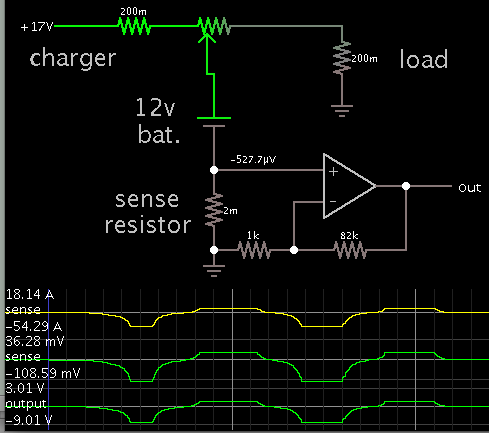
any bode can help me about bidirectional dc current sensing with 358 or 324 op amp ? need its output read form mcu. i was try on Google , but not get it .
 

I have need to read 50 amp DC. for inverter.
1- as on load ( when inverter on , now charging off)
2- as on charging mode (now invereter off ,charging on )
 

Normal method is to use differential amplifier with bipolar ADC and bipolar supply.

Single supply operation requires V+/2 bias for 0 current but still requires Differential Op Amp on current shunt resistor using precision V+/2 reference.

To limit power dissipation in shunt resistor, choose max drop 50mV for 2.5W max or smaller. Thus Differential amp must be very low input offset or chopper type.

If you are lost... then look for high side current shunt power sense chips. Lots to choose from distributor sites.
can u post here any sch ?
i use like this but not as well as .
 

Attachments

  • gif.latex0.gif
    gif.latex0.gif
    871 bytes · Views: 263
  • ofsetamp0.png
    ofsetamp0.png
    7.1 KB · Views: 205
Last edited:

I dont have a sch. handy. But your 50m Ohm shunt will dissipate 125 watts and is not differential balanced for common mode rejection.

I suggest you review the current sensor chips with current direction flag using unipolar supply.

Or a good battery management chip.

The AS8510 is a virtually offset free, low noise, two channel
measurement device. It is tailored to accurately measure battery
current from mA range up to kA range in conjunction with a 100 µΩ
shunt resistor in series with the battery rail.


no no sir shunt value is
0.001 Ohm .
 

Full Rate of current will produce 50mV across the shunt resistance.So, the circuit should be designed when this voltages is appeared at the input of the OpAmp.
If you intend to switch other circuits only, a precise comparator will be better rather than a simple OpAmp.
Operation Amplifiers can also act as comparator but they have hysterisis ( foldback ) therefore using a precise comparator with a voltage reference should be better..
 

To convert +-50mV shunt to 0~5V, You need a gain of 50 and output offset of V/2 or 2.5V
To get 0.1% accuracy the input offset must be <50uV.

One such solution looks like this chip which has zero-drift architecture and works well with shunts as low as 10mV max.
50V/V: INA282 Vio=+/-20uV typ.

https://www.ti.com/lit/ds/symlink/ina282.pdf
 

Use two op-amps (LM358) the current direction will be opposite while charging than in inverter mode, use a diode in series with one of the op-amp so that your ADC doesn,t get negative voltage like this.
 

Attachments

  • sine_ckt2.pdf
    198.6 KB · Views: 207
  • Like
Reactions: sahu

    sahu

    Points: 2
    Helpful Answer Positive Rating
Use two op-amps (LM358) the current direction will be opposite while charging than in inverter mode, use a diode in series with one of the op-amp so that your ADC doesn,t get negative voltage like this.

boos u tell me like this type sch ?

IN4148 drooped 0.350 volt then , our gain formula whats ?
have u any guidens for it , those help me lot

sorry my bad English .
 

I had a backup power system with batteries and PV panels and a 2500W sinewave inverter. I too wanted to construct an ammeter, which would give a net reading on the battery bank.

I wanted to do it with one op amp.

It would require a bipolar supply. Sometimes I would have a negative differential on the wire, sometimes positive.

I continued to think about it. I realized I would have large outgoing A, but less incoming A. So I wondered if I could manage to get less gain in one direction, and higher gain in the other direction.

Furthermore it should give a '0' reading when there was zero current flow. This would require careful adjustment capability. More design effort.

I was not sure I could construct such a meter. Anyway I decided it was too much effort, compared to using two separate meters.
 

yes it so complicated with 1 adc .as per my knowledge . but I'm 200% sure , here most intelligent person in this forum . those can solve our problem.
 

Sahu you always forget (helped me) button, Actually there are variables in this circuit which can be adjusted for the correct Gain but this is only possible if you construct this project. BTW the diode drop can be compensated in software.
 

Sahu you always forget (helped me) button, Actually there are variables in this circuit which can be adjusted for the correct Gain but this is only possible if you construct this project. BTW the diode drop can be compensated in software.
can u give example here ?
 

This simulation illustrates what you're looking for.

3293603600_1416858063.png


The potentiometer was dialed from left to right. It mimics charge and discharge sessions.

The sense resistor can be several inches of wire. You're likely to find it dissipates a few watts as heat, depending on how much power you draw from the battery.

I constructed only the section which measures charge current.

To measure outgoing amperes I used a meter which you place against the wire.
 

Status
Not open for further replies.

Similar threads

Part and Inventory Search

Welcome to EDABoard.com

Sponsor

Back
Top