Continue to Site

Welcome to EDAboard.com

Welcome to our site! EDAboard.com is an international Electronics Discussion Forum focused on EDA software, circuits, schematics, books, theory, papers, asic, pld, 8051, DSP, Network, RF, Analog Design, PCB, Service Manuals... and a whole lot more! To participate you need to register. Registration is free. Click here to register now.

voltage flow - 1 direction only

Status
Not open for further replies.

jayc73

Newbie level 5
Joined
Oct 20, 2014
Messages
10
Helped
0
Reputation
0
Reaction score
0
Trophy points
1
Activity points
116
Hi all,
I'm building a small high voltage project and I'm a little stuck.
Basically I'm building a spark plug tester .
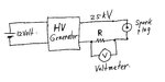
There are 2 contact plates that the spark plug touches and in testing operation the contact plates receive 25kv to ignite the spark plug.
The whole system is run from a 12v dc power supply and a chain of caps and diodes generate the high voltage (off the shelf high voltage generator)

I wish to add an Ohm meter to check the spark plug resistance which will be on a seperate circuit and isolated from the dc power supply when the high voltage generator is in use.
Basically a 2 way switch to use either the Ohm meter or the hight voltage generator independently of each other.

Here's where I'm stuck.
The contact plates which touch the spark plug will be wired directly to the HV generaror.
I wish to wire the Ohm meter directly to the same 2 contact plates but how do I protect the Ohm meter from a 25kv "back charge"

I had thought of using a switch or a relay to break the circuit but I fear the high voltage will jump across the switch or relay contacts.

The Ohm meter operates on 6v-18v dc if it of any help.

Thanks,
Jay
 

Jay,
1. Voltage does not flow; current flows.
2. You can’t do what you are proposing using an Ohmmeter.
3. In order to measure the resistance of the spark plug you need to measure current flowing through it.
4. I suggest you do this as in the attached the drawing.
5. I assume that you can maintain the arc for a few seconds in order to give you time to make the voltage measurement.
6. I don’t know what current will flow through the spark plug, so I would use a 10 Ohm resistor initially.
7. The current can be calculated by I = V/10 where V is the voltage measured by the Voltmeter.
8. Assuming that your high voltage generator is generating close to 25 kV, then a resistance of the spark plug can be calculated by Rs = 25000/I.
9. If the current is in Amps, then the resistance calculated will be in Ohms.
10. Be careful you don’t electrocute yourself.
 

Attachments

  • Spark plug current.jpg
    Spark plug current.jpg
    173.6 KB · Views: 129
  • Like
Reactions: jayc73

    jayc73

    Points: 2
    Helpful Answer Positive Rating
Did you want to measure the resistance during the spark? That is best done with a small series resistor to measure voltage drop. Faraday during his time discovered that contact resistance of an Arc was inversely proportional to the amount of discharge Q=CV

Before you design anything, write down all your inputs and outputs desired. The arc rise time will be a nanosecond or less unless limited by series inductance.
 

Thanks guys :cool:

I just want to measure the resistance without the spark.
In a nutshell ,
switch position 1 (position 2 isolated)- ignites the spark plug
Switch pisition 2 -(position 1 isolated) measure resistance.

Most spark plugs use an internal resistor to eliminate RFI.
As the plug wears /deteriorates the internal resistor does too.
I wanted to be able to perform 2 independent tests while the spark plug is touching the same 2 cotact plates.

Thanks again ,
Jay
 

Resistance in a spark plug can also be present as:

(a) the size of the gap

(b) the shape of the electrodes (sharp vs. rounded edges).

These are a different characteristic from ohmic resistance (although they are a kind of resistance). They have to do with the volt level required to jump the gap. Then after that possibly the volt level which is needed to sustain a spark, at a given amount of current.
 

I don't think you need 25 KV, the voltage rating of the gap is proportional to the compression rating, so 4 KV is more then enough for air. See :- https://en.wikipedia.org/wiki/Paschen's_law , gap = .025", pressure = 760 Torr (Atmospheric)
As I understand it, the spark plug will contain something like a 22K resistor. So if your HV supply has a 22K resistor in series with it, as you wind the voltage up, it will increase until the gap fires, then the voltage will fall to 1/2 (for a good internal 22k resistor), if the internal suppressor resistor is 220K, the the voltage will only fall to 220/242 of the firing voltage. If you replace the 22K series resistor in the PSU with say a 1M ohm, then at some calibrated output ( 1KV?) the voltage at the tip would be (insulation resistance)/ (insulation resistance + 1 M Ohm) times the 1 KV or a good plug would measure over 900V.
So you need a variable PSU, HV voltmeter and a couple of resistors.
Frank
 

Not sure how you could measure the resistor in that situation. As it is in series you could only effectively measure between the cap and centre electrode and not the body of the plug. In effect you would be measuring just leakage from moisture/carbon deposits etc. A relatively low value resistor in series with that would not give any useful info, or am I misunderstanding what you are trying to do.
 

Spark plugs have the similar avalanche characteristics as SIDAC's.

That includes;

Peak On-state Voltage, VTM
Dynamic Holding Current, IH
Peak Repetitive Pulse Current, ITRM
(Negative) Switching Resistance, Rs

A better answer comes from the best question.

Which characteristics are most important to a good plug?

The added internal positive R, the negative R, both? the holding current, the breakdown voltage ? Or maybe junction capacitance? ( all insulators are dielectrics!)

SIDAC.jpgSIDAC2.jpgSIDAC3.jpg

BTW, You only need ~3kV to fire a good plug at 1 atmosphere and 4x3kV at ~8 Atm. for 8:1 compression, unless it is fowled with oil...

THen if it only positive R, do you need help to make a relaxation oscillator to measure the voltage/current swing and thus R.

Of course you can use an ohmmeter if you short the electrodes with a probe, but that's too obvious.
 

Status
Not open for further replies.

Similar threads

Part and Inventory Search

Welcome to EDABoard.com

Sponsor

Back
Top