Continue to Site

Welcome to EDAboard.com

Welcome to our site! EDAboard.com is an international Electronics Discussion Forum focused on EDA software, circuits, schematics, books, theory, papers, asic, pld, 8051, DSP, Network, RF, Analog Design, PCB, Service Manuals... and a whole lot more! To participate you need to register. Registration is free. Click here to register now.

pcb layout for seven segment using PIC18f

Status
Not open for further replies.

internetuser2k13

Member level 3
Joined
Aug 10, 2013
Messages
56
Helped
0
Reputation
0
Reaction score
0
Trophy points
6
Location
pakistan
Activity points
408
HI,
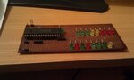
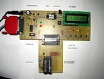
i want to make a PCB board which contains the things for different port like 7 segments ,led ,LCD etc

i cant purchase the board because of some reason.

but i want to make a board and add component as i get my saved pocket money with the passage of time,

Can you please provide me the PCB layout ??

its beginner level with PIC.
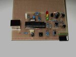
using 18f452.

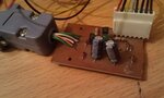
i made the generic board where i can burn the code in PIC.
 

Attachments

  • IMAG0069.jpg
    IMAG0069.jpg
    610.5 KB · Views: 159
  • IMAG0071.jpg
    IMAG0071.jpg
    625.4 KB · Views: 152

Hi,

So you want a pcb for a diy development board, but to your own specification.

You will probably find it much easier to design one yourself, then you can put things exactly were you want them.

However as you progress you will probably find you need to change things, so I find its better to design two boards.
One board will hold a psu 12v 5v 3v3, a row of leds as you have now, some switches or a keypad and say just a simple 16 x2 lcd plus the micro. (a 4520 is a much nicer and compatible chip next time you get one)

The second board will plug in to the first board and contain all your other i/o devices like 7 seg, glcd and sensors etc etc

Looks like a jdm programmer you have there, so if it programs the 452 ok then I would get a 2550/4550 chip and make yourself a basic Pickit2 programmer /debugger + tools , a really great device.
Plans all over this forum, but go for one that uses all microchips firmware .. v 232..

There are plenty of free schematic and pcb layout tools out there like Eagle etc , give them a go, plenty of help here if you get stuck.

Some pictures below to give you some idea of simple diy boards I made when I first started again in micros.
 

Attachments

  • 2007-01-31 002.jpg
    2007-01-31 002.jpg
    78.1 KB · Views: 153
  • pk2mini.jpg
    pk2mini.jpg
    75 KB · Views: 157
  • minipk2.jpg
    minipk2.jpg
    66.6 KB · Views: 140
so advice me what should i do first..
????
and what kind of step i have to taken??
i want to follow you.
 

Hi,

I cannot really take you though every step of designing a development board that only you know what you want.

Looking back at some of your posts it seems you are having difficulty in getting going with programming , so my thoughts tend to be that you first need to get into coding properly and then the hardware should naturally follow on as you understand the micros better.

While the 18F chips are good and generally better than most 16F chips, most tutorials are for the 16F chips and need a little work to convert them to 18F code.

However there are a few 18F tutorials and I have put the links below.
The first one has examples in both C and Assembler so look at them both and see if you can follow them, some folk find they can understand C better the Assembler or the other way around.

Also look at the others links and see if any of those are easier for you to follow, they are beginners stuff like hello world and led / delay flashers but we all started with them.


**broken link removed**

**broken link removed**
 
  • Like
Reactions: Allen6502

    V

    Points: 2
    Helpful Answer Positive Rating

    Allen6502

    Points: 2
    Helpful Answer Positive Rating
This tutorial is a modular way of adding interfaces one at a time. Though it was designed for PIC16F family of chips it can be easily be ported to PIC18F.

http://www.winpicprog.co.uk/pic_tutorial.htm

Both hardware and software in assembly are included.

Allen
 
  • Like
Reactions: wp100

    wp100

    Points: 2
    Helpful Answer Positive Rating
This tutorial is a modular way of adding interfaces one at a time. Though it was designed for PIC16F family of chips it can be easily be ported to PIC18F.

http://www.winpicprog.co.uk/pic_tutorial.htm

Both hardware and software in assembly are included.

Allen

Hi,

Yes thats a very good tutorial but did not include it as its all assembler though there is a partial C version of it here.
http://www.electro-tech-online.com/articles/nigel-goodwins-tutorials-in-c.467/


internetuser2k13

Your existing micro board, does it program and work ok ?
Though it only has leds, you can still run lots of code examples on a board like that.
Adding just one or two simple switches will really increase its abilities.

Cannot see any capacitors around your crystal ?
Also wondered what the led between pin 1 and 40 is connected to ?
Putting a 100nf close to the Vdd and Vss pins is also a good thing to avoid power line interference.
 
Hi,

internetuser2k13

Regarding your other forum post, Proteus does have seven segment leds, have a look at this project.
**broken link removed**

It uses a Pic18F and Microchips latest C XC8 compiler (free download) and I have just complied the code in MPlab X ( free download) and it builds straight away and ran on proteus as you can see from my own screenshot.

( MplabX and XC8 will run separately and Ok with Mplab IDE and other C compilers on your PC)

If you can build and simulate it, then with just changing the chip reference to a 452 and config to Crystal it should run on your hardware which you could even use your existing leds to a least show the program is counting.

Give it a try and let us know how it goes - and no , I do not have a clue about C either, I use assembly

- - - Updated - - -

Hi,

As said, just change the chip to 452 and set up the 452 configuration bits for WDT OFF and OSC HS and it runs fine in simulation
 

Attachments

  • 000162.jpg
    000162.jpg
    86.2 KB · Views: 127
  • 000163.jpg
    000163.jpg
    96.2 KB · Views: 139
the down row of LED connected to port B
and upword row is connected to PORTD.
all the connection are in down side of the board.
i tested the portB led's by loading the HEX file and its working fine.

- - - Updated - - -

actually i was finding the seven segment LED package for PCB.
because i want to design own board which contain LED, 7 segment etc as the work progress other things also gona added :)


Hi,


Here is the .hex code from that 452 7 segment example.
It should run on your portb leds ok just to prove the program is working; do not forget the count up down switch or just wire that pin to pos or neg via a 10k resistor.

If that works ok , then try to convert the pic18 code config values and chip type over to your 452 chip.
Once you know how to do that then you can run all those other examples ..
 

Attachments

  • 7-Segment.X.production.zip
    489 bytes · Views: 111
Here is a schematic of a 40 pin PIC dev board. **broken link removed**

It is cheaper to buy this board than redesigning a PCB and soldering components.
 
can you provide me its PCB LAYOUT. i dnt want to make it suddenly , gradually i will work on PCB. am student , not easy to pay money from my pocket money that why i was asking
 

The PCB setup charges will be around Rs.450. For that price you can buy the board itself. Ask the vendor to provide PCB layout files. I don't have it.
 
Status
Not open for further replies.

Similar threads

Part and Inventory Search

Welcome to EDABoard.com

Sponsor

Back
Top