Continue to Site

Welcome to EDAboard.com

Welcome to our site! EDAboard.com is an international Electronics Discussion Forum focused on EDA software, circuits, schematics, books, theory, papers, asic, pld, 8051, DSP, Network, RF, Analog Design, PCB, Service Manuals... and a whole lot more! To participate you need to register. Registration is free. Click here to register now.

Designing Regulated Power supply

Status
Not open for further replies.

Eshal

Advanced Member level 1
Joined
Aug 29, 2012
Messages
470
Helped
16
Reputation
32
Reaction score
15
Trophy points
1,298
Location
Nowhere :)
Activity points
5,149
Hello all.

Here is the website I am using for help as my project.
**broken link removed**

This image is extracted from the above link.
Capture.PNG
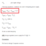
Can you tell me where does the red box formula come? How to derive this formula?

I know 1.41 is the drop of the bridge but this formula doesn't seems to be correct to me. Help me.

Thanks.
 

Hi,

i think you found a mistake.

it should be: VdcNL = Em = Erms x 1.41; (Multiply instead of divedy by 1.41)
Then the formula makes sense.

You can confirm it on your given http site with "Step 5: selecting transformer" where the formula is correct.

Klaus
 
  • Like
Reactions: Eshal

    Eshal

    Points: 2
    Helpful Answer Positive Rating
1.41 is not the drop of the bridge in those equations, it is the conversion factor from RMS voltage to peak voltage (since the filtered output voltage from a diode rectifying AC is near the peak AC voltage).
 
  • Like
Reactions: Eshal

    Eshal

    Points: 2
    Helpful Answer Positive Rating
Design site has error in the design calculations for RMS >Peak near beginning.

So there are many more variables which are affected by your budget for cost and temp. Rise (reliability)

Ic=Cdv/dt=1A letting dt=T=10ms, where R is effective load of 5v/1A=5Ω. The capacitors should have an ESR much lower than this such as 5% or 25mΩ. This biggest cost may be the transformer or capacitor or LDO or diode bridge depending each choice , a balanced approach for lowest cost may be optimal but have poor reliability, so heat rise analysts is needed.


If good Schottky diodes, Vf=0.5V@5A, Silicon power Vf=1V@5A

Use a better LDO with 0.3V drop which I recommended.


capacitor size is critical.

Recall Ic=Cdv/dt=1A & Vp=1.414*Vrms-Vf
where Vf is doubled for a full bridge, and lower for Schottky vs Silicon


Thus C= I * dt/dv where dt=2/f (line f ) or 10ms for 50Hz
Ripple=dv may end up being large such as 30-40% at Imax. Thus Voc , open circuit increases with ripple voltage, LDO drop, diode drop and smaller caps. Try 4700uF >=12V

Vrms =(Vo (DC)+ V(LDO drop) + Vripple + Vdiodes)/1.414


With success your LDO , Cap and bridge will not be hot and your Vrms transformer need only be 8W at <<9V.
 

@KlausST & @crutschow & @SunnySkyguy
Thanks for correcting me.
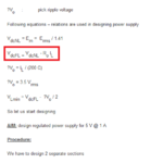
Where does the red boxed equation come from in the image below? How to derive it?
Capture.PNG

@SunnySkyguy
What is LDO?
Why did you let dt=T=10ms? why not 20ms or something else? What is theory behind selecting dt?
This supply has output current rated at 1A. But here you have write capacitor current Ic=Cdv/dt=1A. Do you think the capacitor current is also the output current of the supply? Don't you think there is a regulator after the capacitor which also consume some current so capacitor current should some higher value than 1A?
What is dt=2/f (line f)
What is Voc? Is it voltage of capacitor?

Thanks.
 

VFL(full load) = VNL( no load) minus secondary winding drop I*Rs

Low Drop Out=LDO linear regulators are much lower than they used to be ... was 2.5 now with FETs is <<0.5V
 
  • Like
Reactions: Eshal

    Eshal

    Points: 2
    Helpful Answer Positive Rating
.................................
Why did you let dt=T=10ms? why not 20ms or something else? What is theory behind selecting dt?
This supply has output current rated at 1A. But here you have write capacitor current Ic=Cdv/dt=1A. Do you think the capacitor current is also the output current of the supply? Don't you think there is a regulator after the capacitor which also consume some current so capacitor current should some higher value than 1A?
What is dt=2/f (line f)
dt is equal to the time between the cycle peaks for a full-wave rectified output which is dt=2/f. For a 50Hz line frequency that gives 10ms. It would be 8.33ms for a 60Hz line frequency. The capacitor has to provide the output current between the peaks since it is recharged only at the peak of each rectified sinewave.

Typical series regulators take very little current to operate. For example the common LM317 takes less than a mA to ground under normal operation. The circuit is designed such that the rest of the operating current (less than 10mA) appears as part of the output current.
 
  • Like
Reactions: Eshal

    Eshal

    Points: 2
    Helpful Answer Positive Rating
@SunnySkyguy
VFL(full load) = VNL( no load) minus secondary winding drop I*Rs
It means in the red box it is (Ro)(IL). This is wrong? Because you are saying it is winding drop but the red box equation has full load output current. Right?

@crutschow
Still confused where does dt=2/f come from? What does it mean? why it is 2 in numerator? is it due to the full cycle means upper cycle and lower cycle?

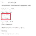
Also tell me where does 200 in the denominator come from and where does 3.5 come from in the red box equation in the below picture?
Capture.PNG

thanks all.
 

..........................
@crutschow
Still confused where does dt=2/f come from? What does it mean? why it is 2 in numerator? is it due to the full cycle means upper cycle and lower cycle?
The duration of one unrectified cycle is 1/f. A full-wave rectified signal has two peaks per cycle so the time between peaks is 2/f.
Also tell me where does 200 in the denominator come from and where does 3.5 come from in the red box equation in the below picture?
Sorry, I don't know offhand where they came from. :-(
 
  • Like
Reactions: Eshal

    Eshal

    Points: 2
    Helpful Answer Positive Rating
The article about ps design is based rather on empirical observations then exact theory. Why constant 200 is used it is best to ask author.

Ripple voltage on smoothing capacitor depends on rectifier topology, transformer properties, condenser capacitance, load current...
Vo formula describes that capacitor reactance is considered as 1/(200*C) regarding rms ripple voltage...
 
  • Like
Reactions: Eshal

    Eshal

    Points: 2
    Helpful Answer Positive Rating
@crutschow
Its ok dear. You helped me a lot. Thanks.

@Borber
The article about ps design is based rather on empirical observations then exact theory. Why constant 200 is used it is best to ask author.
what do you think, I would had not asked everything about this to the author? Obviously I did but I am not receiving any reply from him. And after clearing all confusion I will start designing my own but only equations are making crazier me.

Ripple voltage on smoothing capacitor depends on rectifier topology, transformer properties, condenser capacitance, load current...
Vo formula describes that capacitor reactance is considered as 1/(200*C) regarding rms ripple voltage...
I understand what factors depend upon the ripple voltage but why 200? It is 5V and 1A power supply, if it is 35V and 2A power supply then still I need to use this 200 or any other factor? How to evaluate it technically?

Thanks,

Regards,
Princess
 

Imagine: 2*pi*f is for 50Hz about 314 and for 60Hz about 377 and capacitor reactance is 1/(2*pi*C). If you accept crazy formula that ripple voltage is product of load current and some "sort" of capacitor reactance then constant 200 covers this "sort" of reactance. Without any experiment you have to believe to author of the article.
Technical evaluation of crazy formula requires suitable transformer, rectifier bridge, few different smoothing capacitors, suitable resistors which will represent different loading of rectifier and AC rms multimeter. Following procedure is obvious...but it's up to you.
 
  • Like
Reactions: Eshal

    Eshal

    Points: 2
    Helpful Answer Positive Rating
@Borber
I think you are right dear. Your answer seems correct. This is a good point.

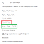
Here is the image below, can you tell me from where 3.5 come in the red boxed equation and how did the author derived the green boxed formula?
Capture.PNG

Thanks
 

3.5 is magic number determining relation between ripple voltage rms and peak value.
Green box formula tells you that minimums of output voltage are equal full load DC average voltage minus half of peak ripple voltage.
 
  • Like
Reactions: Eshal

    Eshal

    Points: 2
    Helpful Answer Positive Rating
I thought you were trying to design a 50 or 60 Hz linear drop-out (LDO) regulator thus 50Hz rectified is 10ms. In estimating ripple the storage Cap we use. Ic=C dv/dt

since I assume the author lives in the land of 50 Hz , the diode bridge doubles the frequency , thus dt=10ms so ... Re-arranging std formula,

dv=Ic dt/C since |Ic| = IL and IF we assume the ripple dv could be as much as 50% of Vo ...
50%Vo= IL 10ms /C or ?Vo= IL *2/(100*C)

?Vo = IL / (200 C) another error?

Here's another error where he assumes the DC out of a centre tapped transformer is the same of a full bridge (aka voltage doubler)
1) Center tap transformer of 9 – 0 – 9 or 7 .5 – 0 – 7.5 secondary voltage
2) Transformer Without center tapping either 0 – 15 or 0 – 18 secondary voltage

This is only true is you ignore the tap and use a full bridge in both cases. Normally one uses a half bridge or 2 diodes from a centre tped transformer to get twice the current at half the voltage.


This design article has at least 3 major flaws in design errors, assumptions or oops. Hence don't use it.
 
  • Like
Reactions: Eshal

    Eshal

    Points: 2
    Helpful Answer Positive Rating
@Borber
Got it. Explained well my dear. ;-)

@SunnySkyguy
I thought you were trying to design a 50 or 60 Hz linear drop-out (LDO) regulator thus 50Hz rectified is 10ms.
I do live in 50Hz country. But I am not going to design this power supply instead I will design P.S. rated at 35V @5A
dv=Ic dt/C since |Ic| = IL and IF we assume the ripple dv could be as much as 50% of Vo ...
50%Vo= IL 10ms /C or ?Vo= IL *2/(100*C)

?Vo = IL / (200 C) another error?
If we consider less than 50% of Vo for example, 10% of Vo then this formula, with same derivation as you did, would look like something this,
After re-arranging the standard equation
dv=Ic dt/C since |Ic| = IL and IF we assume the ripple dv could be as much as 10% of Vo ...
10%Vo= IL 10ms /C or ?Vo= IL /(10*C)
Is it right?
The less output ripples are considered then the more DC output we will get. Right? That's why I choose 10%.
Here's another error where he assumes the DC out of a centre tapped transformer is the same of a full bridge (aka voltage doubler)
1) Center tap transformer of 9 – 0 – 9 or 7 .5 – 0 – 7.5 secondary voltage
2) Transformer Without center tapping either 0 – 15 or 0 – 18 secondary voltage
This is only true is you ignore the tap and use a full bridge in both cases. Normally one uses a half bridge or 2 diodes from a centre tped transformer to get twice the current at half the voltage.
I will not use center-tapped transformer in my design.
This design article has at least 3 major flaws in design errors, assumptions or oops. Hence don't use it.
I am not using it but I am taking help from this website and ofcourse you are here to help me. :)
 

@SunnySkyguy, @Borber, @crutschow and @KlausST
Why are you not replying to this thread? Did tell anything bad to you guys? Respect a girl by posting comments to her post and thread. :D :wink: heheheheheh...
 

I am not used to manipulate with differential equations like article author does. Try to remember everything and stick with it.
 

Status
Not open for further replies.

Similar threads

Part and Inventory Search

Welcome to EDABoard.com

Sponsor

Back
Top