Continue to Site

Welcome to EDAboard.com

Welcome to our site! EDAboard.com is an international Electronics Discussion Forum focused on EDA software, circuits, schematics, books, theory, papers, asic, pld, 8051, DSP, Network, RF, Analog Design, PCB, Service Manuals... and a whole lot more! To participate you need to register. Registration is free. Click here to register now.

[AVR] [ATMEGA] Generating 50 Hz Sine wave using SPWM in atmega16

Status
Not open for further replies.

AtMega32

Junior Member level 3
Joined
Nov 11, 2013
Messages
30
Helped
2
Reputation
4
Reaction score
3
Trophy points
8
Activity points
277
I was following this tutorial
Written by tahmid,

I am confused with couple things,

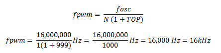
  • Why TOP value is chosen as 999 and not something else (like 1200 or 499) is this just to set the PWM frequency to 16 Khz or is there some other reason ??
  • Why sine peak value is taken as 990 and not 1000 or 256 or anything else ???

    Most confused part is SET_Frequency
  • Lets say i want to take 128 samples of sine wave for the half cycle instead of 32 (tahmid taken that much)
    Frequency of PWM is 16 Khz (62.5 us) as it is calculated earlier with this formula
    frequency.PNG


    Output frequency which want is 50 Hz (20 ms) for half cycle 10 ms

    for my case with 128 samples, to calculate set frequency

    Set Frequency = 2^16 / [(no. of sine values) * (no. of times each value is called)]
    no. of times each value is called can be calculated using this as tahmid has done that in that blog
    2*128*(62.5 us) * no. of times = 20 ms
    no. of times each value is called = 1.25
  • it is not an integer so do i take it as 2,

    Set frequency = 2^16 / (128 * 2) = 256
  • is this the correct way to calculate set frequency ?
  • table pointer new is to be right shifted 9 times as to get a number between 0-128, and calling each value 2 times to complete the half cycle.
  • but all the calculations go wrong as the output frequency desired is 50 Hz but with no. of times each value is called as 2 and set frequency = 256 , i would get
    2* 62.5 us * 128 * 2 = 32 ms = 31.25 Hz and not 50 Hz


thought of pm'ing him but he haven't replied to my previous pm so may be he is busy, so can someone here helps me understand few things
 

Hi;

TOP value: it is used to get exactely 16kHz of PWM frequency.
SINE PEAK: ifthere are MOSFETDRIVERS used they can not output 100% high. Therfore this ensures a small LOW time.
SAMPLES per halfwave:for 128 samples per halfwaveyou need 50Hz x 128 x 2 = 12.8kHz set frequency
INTEGER: You must take an integer value. This can be done by choosing the right TOP value.

16M / 12800 = 1250; --> set top value to 1249.
a min LOW of 1% should be enough. therfore calucalte sin max = 1250 x (100-1)% = 1237.


Hope this helps
Klaus
 
KlausST: First of all thanks for taking time to reply

I got it about TOP and sine maximum value.
we can also reduce frequency with pre-scalar right ?

So My PWM frequency would be 12.8 KHz (78.125 us) right ?

with that PWM frequency i need to call each sine value only once ?

Now the SET_FREQ = 2^16 / [(no. of sine values) * (no. of times each value is called)]

SET_FREQ = 65536/128 * 1 = 512

So that means every time i need to increase the TBL_POINTER_NEW value by 512.

TBL_POINTER_RIGHT_SHIFT we need to make is 16 - 7 = 9 right ?

2^7 = 128

So with every interrupt just update the tbl pointer new value and call the sine value.

have i done it right ?

could you please tell me or point me to a tutorial which shows how to do the calculation step by step, i am too confused about the procedure (what to calculate after what) to follow while calculating,
 
Hi,

...prescaler: I see no need to change prescaler...
...PWM frequency: yes, it is 12.8 kHz
...call sine value: right, only once
...SET_FREQ: i didnt see the blog, but i think its for varying sine frequency like for an adjustable sinewave generator

If you don´t want to change your sine frequency, then it is easier to generate a table with 128 entries (samples_per_sine).

TABL_POINTER: if you have 128 table_entries then increase pointer by 1

tutorial, sorry i can´t help you

*********
lets see what happens.

Klaus
 

Thank you,
Let me change the code given by tahmid in his blog with mine calculation and see what result i get.
can you please tell me from where you learn or any good site to learn this
 

Hi

Where to learn from...

I am curious on everythig that has to do with technics, physics and mathematics..

Mostly learning by doing

Klaus
 

https://tahmidmc.blogspot.com/2013/02/sine-wave-generation-with-fast-pwm-mode_2525.html

Can someone go through this tutorial and tell me the steps Tahmid followed for the calculation.

I have completely understood the way KlausST told earlier.
I want to learn how tahmid has done it. Only one change to his code, 128 samples instead of 32 (no need to generate the sine table, can do it my self), keep the PWM frequency as 16 Khz.

just explain me the step by step procedure (calculate this after this etc.)
 

Hi,

I didn't see tahmid's blog, but from what you post it might be a DDS solution.

IF so, then he calculates the new phase angle, looks into the table for the nearest entry and outputs it to pwm.

Only guessing...

Klaus
 

KlausST: can you please just go through that link, just check the code, i guess you're quite intelligent to understand the code and don't have to read the whole article.

Isn't it the same circuit or same procedure followed for Inverter, with this output if i use one transformer then i can get 12 v DC to 220 v AC ?
 

Hi ... whoever...

i just had a look into tahmid´s tutorials.

It is a solution similar to DDS.
There is one counter called TBL_POINTER_NEW (16 bit, 0..65535) for the phase. It represents an angle of 0...180 degree.
So 65536 = 180 degree = one halfwave.

With 50Hz you have 10 ms for one halfwave. Within 10ms and a pwm frequency of 16.000 Hz you get 160 interrupts.
Within 160 interrupts there should be the value of 65536.
This means per interrupt you have to increment the TBL_PINTER_NEW by 65536 / 160 = 409.6. rounded = 410.

Also the 65536 represent 32 entries of the table. Devide 65536 by 32 = 2048, which is 2^11.
This is why he shifts the TBL_POINTER_NEW 11 times right and get values of 0...31 ... the table entry. Rounding is not necessary.

(btw: because of using 410 instead of 409.6 you will see a sine frequency of 50.0488 Hz)

So what happens: (every line the TBL_POINTER_NWE is incremented by 410, each line shows 1/16.000s interrupt.
TBL_POINTER_NEW; Table_entry
0; 0
410; 0
820; 0
1230; 0
1640; 0
2050; 1
2460; 1
2870; 1
3280; 1
3690; 1
4100; 2
4510; 2
...
64780; 31
65190; 31
64; 0
474; 0
...

With that solution you are able to adjust the 50Hz with a step size of 0.122 Hz.
**********
If you now want to use this solution with 128 Table entries then:

65536 represent 180 degree = 128 entries.
65536 / 128 = 512, which is 2^9.
So don´t shift 11 times right but 9 times right.

--> create 128 entires table, change shift from 11 to 9.
Everything else stays the same.
******

I hope there was no mixing up in my brain. Therfore i ask someone to try this and correct it.

Hope this helps
Klaus
 
Thank you KlausST for taking time and going into that tutorial.

Thanks for a detailed explanation now i understood every bit of that code, that step by step calculation helps me a lot. Thank you
 

KlauST: I think for 128 entries, i don't there is any need of tbl_pntr_old.
no need of this comparison as well, if (TBL_POINTER_NEW < TBL_POINTER_OLD).
instead of this, i think i can do something like this inside interupt function


Code C - [expand]
1
2
3
4
5
6
7
8
9
10
11
12
13
14
15
16
17
18
19
20
21
22
23
void interrupt() org IVT_ADDR_TIMER1_OVF{
     TBL_POINTER_NEW = TBL_POINTER_NEW + SET_FREQ;
          //sending signal every 10 ms,
           if (Direction == 0){
              MOSA = 0;
              MOSD = 0;
              MOSB = 1;
              MOSC = 1;
              Direction = 1;
           }
           else{
                MOSB = 0;
                MOSC = 0;
                MOSA = 1;
                MOSD = 1;
                Direction = 0;
           }
        TBL_POINTER_SHIFT = TBL_POINTER_NEW >> ;   
        DUTY_CYCLE = TBL_POINTER_SHIFT;
        TBL_POINTER_SHIFT = sin_table[DUTY_CYCLE];
        OCR1AH = TBL_POINTER_SHIFT >> 8;
        OCR1AL = TBL_POINTER_SHIFT & 0x0F;
}


what do you say about this piece of code, please comment
 
Last edited by a moderator:

Hi,

This is only a small part of your code..
i see the timer function running every 10ms and changing the polarity of the bridge output...but is it synchronous to the zero crossing of the pwm values???

Klaus
 

KlausST: bro, i have used the same code as Tahmid has used in his article,. just modified the parts i don't need. highlighted them in red.

TBL_POINTER_OLD is removed as not necessary in my case.

Tahmid has used SREG_I_bit = 1; is it same as sei(); starting the global interrupt ?


here is the complete code, please suggest if any error in the code.

Code:
//----------------------------------------------------------------------------------------
//Programmer: Syed Tahmid Mahbub
//Target Microcontroller: ATMEGA16
//Compiler: mikroC PRO for AVR (Can easily port to any other compiler)
//-----------------------------------------------------------------------------------------  

 [COLOR="#FF0000"]
unsigned int sin_table[128]={0, 24, 49, 73, 98, 122, 146, 171, 195, 219, 242, 266, 290, 313, 336, 359, 382, 404, 426, 448, 470, 491, 513, 533, 554, 574, 594, 613, 632, 651, 669, 687, 704, 721, 738, 754, 770, 785, 799, 814, 827, 841, 853, 865, 877, 888, 899, 909, 918, 927, 935, 943, 950, 957, 963, 968, 973, 977, 981, 984, 986, 988, 989, 990, 990, 989, 988, 986, 984, 981, 977, 973, 968, 963, 957, 950, 943, 935, 927, 918, 909, 899, 888, 877, 865, 853, 841, 827, 814, 799, 785, 770, 754, 738, 721, 704, 687, 669, 651, 632, 613, 594, 574, 554, 533, 513, 491, 470, 448, 426, 404, 382, 359, 336, 313, 290, 266, 242, 219, 195, 171, 146, 122, 98, 73, 49, 24,0};
    [/COLOR] //sine table with 128 entries, Peak value as 999 and 127 entries, zero at the end makes it 128

#define MOSA PORTD0_bit
#define MOSB PORTD1_bit
#define MOSC PORTD2_bit
#define MOSD PORTD3_bit

unsigned char FlagReg;
#define Direction FlagReg.B0
//0 -> MOS A + D
//1 -> MOS B + C

unsigned int TBL_POINTER_NEW, TBL_POINTER_SHIFT, SET_FREQ;
unsigned int TBL_temp;
unsigned char DUTY_CYCLE;

void interrupt() org IVT_ADDR_TIMER1_OVF{
     TBL_POINTER_NEW = TBL_POINTER_NEW + SET_FREQ;
          //sending signal every 10 ms,
           if (Direction == 0){
              MOSA = 0;
              MOSD = 0;
              MOSB = 1;
              MOSC = 1;
              Direction = 1;
           }
           else{
                MOSB = 0;
                MOSC = 0;
                MOSA = 1;
                MOSD = 1;
                Direction = 0;
           }
       [COLOR="#FF0000"] TBL_POINTER_SHIFT = TBL_POINTER_NEW >> 9; [/COLOR]  //TBL_POINTER_NEW is shifted 9 times instead of 11.
        DUTY_CYCLE = TBL_POINTER_SHIFT;
        TBL_POINTER_SHIFT = sin_table[DUTY_CYCLE];
        OCR1AH = TBL_POINTER_SHIFT >> 8;
        OCR1AL = TBL_POINTER_SHIFT & 0x0F;
}

void main() {
     SET_FREQ = 410;
     TBL_POINTER_SHIFT = 0;
     TBL_POINTER_NEW = 0;
     TBL_POINTER_OLD = 0;
     DUTY_CYCLE = 0;
     DDRC = 0xFF;
     DDRD = 0XFF;
     OCR1AH = 0;
     OCR1AL = 0;
     TCCR1A = 0x82;
     ICR1H = 0x03;
     ICR1L = 0xE7;
     //ICR1 = 999 -> TOP -> 16kHz
     TIMSK = 0x04;
     TCCR1B = 0x19;
     SREG_I_bit = 1;
     while(1);
}
 
Last edited:

Hi,

Please make a test or simulation.
The remark says that timer1_ovf happens every 10ms, but it needs to be more often...

There should be 128 table enties plus the limitin 0 giving 129 entries.
Peak in sine table is 990 but remark say 999. I think 990 is ok.

Please try it and write what happens..
Klaus
 

I have generated 127 sine table values and added one extra 0 to make it 128.

Confused over two things

SREG_I_bit = 1; is it same as sei(); starting the global interrupt ????

The remark says that timer1_ovf happens every 10ms, but it needs to be more often...
Why should it be more often , didn't able to understand it ???
the final sine wave frequency would be little less than 50 as instead of repeating the entries 1.25 times it is only taken once.
 

Hi,

You have s sinetable with 128 entries per halfwave. A halfwave is 10 ms. So you need to output a new pwm value 128 / 10ms = 12800 per second.

I'm very sure there must be 128 sine values (plus 1 delimiter, if needed)

Again: try it and tell what happens...

Klaus
 

Calculate Sin table

Hi everyone. I saw Tahmid's Blog. Annd I don't understand why he caculated value in sin_table. I tried calculate with his software( Smart Sine). But Value isn't same in his code. So Who can help me?! please!
 

Hi,

To fetch a sine value from the table takes only a few instructions.

Calculating takes much longer. It simply increases processing load.

Why the values differ...
We don't see how you calculated it and how the results are.
Either we need a crystal ball or more information.

Klaus
 

Hi,

To fetch a sine value from the table takes only a few instructions.

Calculating takes much longer. It simply increases processing load.

Why the values differ...
We don't see how you calculated it and how the results are.
Either we need a crystal ball or more information.

Klaus

oh. Thank you for your reply my coment, but now I was understand method to caculate value of sin table. :)
 

Status
Not open for further replies.

Similar threads

Part and Inventory Search

Welcome to EDABoard.com

Sponsor

Back
Top