Continue to Site

Welcome to EDAboard.com

Welcome to our site! EDAboard.com is an international Electronics Discussion Forum focused on EDA software, circuits, schematics, books, theory, papers, asic, pld, 8051, DSP, Network, RF, Analog Design, PCB, Service Manuals... and a whole lot more! To participate you need to register. Registration is free. Click here to register now.

[SOLVED] circuit bugs :solar charge controller idea

Status
Not open for further replies.

myfaithnka

Advanced Member level 4
Joined
Nov 5, 2010
Messages
106
Helped
2
Reputation
4
Reaction score
2
Trophy points
1,298
Activity points
2,022
hi all,
I am trying to make a simple charge controller using 555 to charge my emergency(6v sla battery) from a solar panel of 12 v.

This is the circuit made i on bread board,

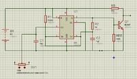
the output pulses drives a mosfet. There i found problems. Oscillations from 555 goes dead and mosfet gets heated.

is there any problem with this circuit? please give your suggestions and corrections.

thanks
 

I'd expect the BC547 to get damaged due to the base being over-driven. There should be a current limiting resistor between it's base and pin 3 of the 555.

Why do you need the BC547, Rb and Rbb anyway? Can't you drive the MOSFET directly from pin 3 of the 555?

Also, what is the purpose of R1? It doesn't seem to have any useful purpose.

i needed an inversion because the mosfet should switch more during low light and less during high light.

r1 is the charging path for oscillation capacitor i assume.

is there any foolish things i have done ?:cry:
 

I think that the timer IC has not been properly configured in astable mode.Check the datasheet.Try either disconnecting the pin 7 or connect the pin 7 properly to the node in the schematic.
 
Last edited:
thank you,i am looking its out put now
 

@ amayilsamy,

Nice schematic --- what is your software?
 

It is proteus from Labcenter electronics... Its good simulation software..
 

@ amayilsamy,

Thank you
 

Too badly designed a circuit. Wrong input to Pin 5 . Direct drive to the transistor from pin 3 and many other mistakes.
 
Status
Not open for further replies.

Similar threads

Part and Inventory Search

Welcome to EDABoard.com

Sponsor

Back
Top