mimorfid
Newbie level 6
Hi,
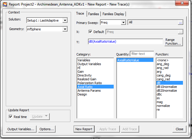
have simulated patch antenna. Since it is corner truncated it should have circular polarisation. In papers circular polarisation is determined on the basis of axial ratio. They have the graph of axial ratio versus frequency. it would be of great help if you suggest how to determine the axial ratio or the circular polarisation in hfss.
have simulated patch antenna. Since it is corner truncated it should have circular polarisation. In papers circular polarisation is determined on the basis of axial ratio. They have the graph of axial ratio versus frequency. it would be of great help if you suggest how to determine the axial ratio or the circular polarisation in hfss.