Continue to Site

Welcome to EDAboard.com

Welcome to our site! EDAboard.com is an international Electronics Discussion Forum focused on EDA software, circuits, schematics, books, theory, papers, asic, pld, 8051, DSP, Network, RF, Analog Design, PCB, Service Manuals... and a whole lot more! To participate you need to register. Registration is free. Click here to register now.

inductive proximity sensor with PIC micro

Status
Not open for further replies.

pasicr

Advanced Member level 1
Joined
Aug 13, 2005
Messages
440
Helped
39
Reputation
80
Reaction score
29
Trophy points
1,308
Location
Macedonia
Activity points
4,213
Hi there, I need to use inductive proximity sensor with three wire (brown (+), blue (-), black (load)), NPN NO tipe, up to 30VDC, with PIC micro,
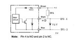
I have PIC MAXI WEB board from Olimex, this board have 4 optocoup. inputs (see attached shematic),
can somebody help how to connect this sensor to this optocouplered input? I will use 12VDC to power sensor,
What is the best way to count detection from this sensor using MIKROC for PIC?
thanks
regards
 

Attachments

  • PIC-MAXI-WEB_sch.pdf
    94.6 KB · Views: 177

datasheet is attached,
the model is
DC 3 wire, NPN NO, Pre Wired, M18, (brown (+), blue (-), black (load)),
regards
 

Attachments

  • datasheet_proximity_sensor.pdf
    227.4 KB · Views: 171

Connect like this....

untitled.JPG

For any sensation the intput will be low..
 

Attachments

  • untitled.JPG
    untitled.JPG
    15.8 KB · Views: 100
  • Like
Reactions: pasicr

    pasicr

    Points: 2
    Helpful Answer Positive Rating
It's open collector output so why pull it up to 12V?
I would pull it up to VDD (which may not be 5V) of the PIC and omit the protection Zener.

Brian.
 
  • Like
Reactions: pasicr

    pasicr

    Points: 2
    Helpful Answer Positive Rating
It's open collector output so why pull it up to 12V?
I would pull it up to VDD (which may not be 5V) of the PIC and omit the protection Zener.

Brian.
It goes to opto-coupler of 330 ohm in series...
the zener is just to ensure the output level when the pin is open...
 
  • Like
Reactions: pasicr

    pasicr

    Points: 2
    Helpful Answer Positive Rating
Venkadesh_M, I understand the working of the circuit and the reason for the Zener but may PC devices run on less the 5V, most of my designs run on 3.3V devices. The maximum input pin voltage in most cases is VDD, I appreciate some pins are 5V compliant. If the resistor pulls the sensor output to VDD rather than 12V, it will always give the right potential for the PIC and no Zener is needed.

Brian.
 
  • Like
Reactions: pasicr

    pasicr

    Points: 2
    Helpful Answer Positive Rating
Isn't there a zener inside the sensor module? The fig. shows there is an internal zener between pins 4 and 3.

Yeah, but can you tell what is Its value?

- - - Updated - - -

Venkadesh_M, I understand the working of the circuit and the reason for the Zener but may PC devices run on less the 5V, most of my designs run on 3.3V devices. The maximum input pin voltage in most cases is VDD, I appreciate some pins are 5V compliant. If the resistor pulls the sensor output to VDD rather than 12V, it will always give the right potential for the PIC and no Zener is needed.

Brian.
Yeah brian I also agree with it, that was a best practice giving VDD as the High voltage, here the optocoupler have 330ohm in series by giving 3.3V that may not turn ON and If a 5V source in the board then no need of additional zener...........
 
  • Like
Reactions: pasicr

    pasicr

    Points: 2
    Helpful Answer Positive Rating
Hi for all,
after your discussion I am confused about connection between inductive proximity sensor and MCU via optocoupler in my case,
can somebody explain what is the best way in this case?
I use PIC MAXI WEB board from Olimex,
best regards
 

hello,

Test before if you have a true open collector on the output..
with no load connected ..must give allways voltage=0V

You can try to connect directly output (open collector) of your sensor to the input of
Olimew card, and pull up this sensor output to the 3,3V.
and power on the (electronic of) sensor by 12V.
but you have no waranty that the output level of the Open collector transistor can
goes under the minimum low level voltage of 3,3V TTL for 0 logic level.
if Not enough saturate.
Only trial can confirm.


Thanks colleagues for your support,
can you see my peace of code (mikroC pro) nd suggest me what I need to change to "read" interrupt from inductive proximity sensor,
I have 3 of them connected on RC2, RG4 and RB4 on my 18F97J60
I used this code for "read" buttons condition until now:
Code:
while (1) {
  
  Read_Time(&sec,&min1,&hr,&week_day,&day,&mn,&year);                           // citaj podatoci od RTC(DS1307)
  
  if(Button(&PORTB,3,1,0)){
      number1 = number1 + 1;
      ShortToStr(number1, prv);
      MMC_Fat_Assign(&filename, 0);
      MMC_Fat_Append();                                    // Prepare file for append
      MMC_RTC_Data[0] = ((hr >> 4) + 48);
      MMC_RTC_Data[1] = ((hr & 0x0F) + 48);
      MMC_RTC_Data[2] = ':';
      MMC_RTC_Data[3] = ((min1 >> 4) + 48);
      MMC_RTC_Data[4] = ((min1 & 0x0F) + 48);
      MMC_RTC_Data[5] = ':';
      MMC_RTC_Data[6] = ((sec >> 4) + 48);
      MMC_RTC_Data[7] = ((sec & 0x0F) + 48);
      MMC_Fat_Write(MMC_RTC_Data, 8); //write data to the assigned file
      MMC_Fat_Write(tab1, 5);
      MMC_Fat_Write(prv, 5);
      MMC_Fat_Write(rtrn,4);
    }
    Display_init1();

    if(Button(&PORTB,1,1,0)){
      number2 = number2 + 1;
      ShortToStr(number2, vtor);
      MMC_Fat_Assign(&filename, 0);
      MMC_Fat_Append();                                    // Prepare file for append
      MMC_RTC_Data[0] = ((hr >> 4) + 48);
      MMC_RTC_Data[1] = ((hr & 0x0F) + 48);
      MMC_RTC_Data[2] = ':';
      MMC_RTC_Data[3] = ((min1 >> 4) + 48);
      MMC_RTC_Data[4] = ((min1 & 0x0F) + 48);
      MMC_RTC_Data[5] = ':';
      MMC_RTC_Data[6] = ((sec >> 4) + 48);
      MMC_RTC_Data[7] = ((sec & 0x0F) + 48);
      MMC_Fat_Write(MMC_RTC_Data, 8); //write data to the assigned file
      MMC_Fat_Write(tab2, 19);
      MMC_Fat_Write(vtor, 5);
      MMC_Fat_Write(rtrn,4);
    }
    Display_init2();

    if(Button(&PORTB,0,1,0)){
      number3 = number3 + 1;
      MMC_Fat_Assign(&filename, 0);
      MMC_Fat_Append();                                    // Prepare file for append
      MMC_RTC_Data[0] = ((hr >> 4) + 48);
      MMC_RTC_Data[1] = ((hr & 0x0F) + 48);
      MMC_RTC_Data[2] = ':';
      MMC_RTC_Data[3] = ((min1 >> 4) + 48);
      MMC_RTC_Data[4] = ((min1 & 0x0F) + 48);
      MMC_RTC_Data[5] = ':';
      MMC_RTC_Data[6] = ((sec >> 4) + 48);
      MMC_RTC_Data[7] = ((sec & 0x0F) + 48);
      MMC_Fat_Write(MMC_RTC_Data, 8); //write data to the assigned file
      MMC_Fat_Write(rtrn,4);
    }
    Display_init3();
    
    Transform_Time(&sec,&min1,&hr,&week_day,&day,&mn,&year);                      // formatiraj gi
    Display_Time(sec, min1, hr, day, mn, year);                                   // prikazigi na LCD
    Delay_ms(150);                                                                // cekaj 50 ms
  
  }

thanks and
regards
 

Status
Not open for further replies.

Part and Inventory Search

Welcome to EDABoard.com

Sponsor

Back
Top