Continue to Site

Welcome to EDAboard.com

Welcome to our site! EDAboard.com is an international Electronics Discussion Forum focused on EDA software, circuits, schematics, books, theory, papers, asic, pld, 8051, DSP, Network, RF, Analog Design, PCB, Service Manuals... and a whole lot more! To participate you need to register. Registration is free. Click here to register now.

Simple Power suply (burned)

Status
Not open for further replies.

luiggipf

Newbie level 5
Joined
Sep 22, 2013
Messages
8
Helped
0
Reputation
0
Reaction score
0
Trophy points
1
Activity points
73
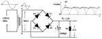
I tried to make a simple power supply with some components that I had lying around, and it just began to make some weird noises, that ended up burning two of the diodes that made up the full-wave rectifier ( using the 4 diodes ).

I do not have much experience yet so I could have done some obvious mistake, that I hope that I could find out here at this forum.

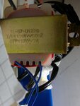
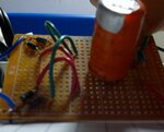
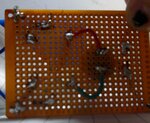
The images show how I set everything up and the specifications of it all.
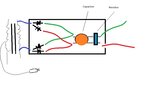
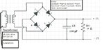
 

Attachments

  • 2013-09-22-022.jpg
    2013-09-22-022.jpg
    1 MB · Views: 85
  • 2013-09-22-023.jpg
    2013-09-22-023.jpg
    1.3 MB · Views: 88
  • 2013-09-22-024.jpg
    2013-09-22-024.jpg
    1.5 MB · Views: 78
  • Drawing.jpg
    Drawing.jpg
    44.3 KB · Views: 92
  • Intended project.jpg
    Intended project.jpg
    62.1 KB · Views: 81
  • My project.jpg
    My project.jpg
    87.1 KB · Views: 82

My internet connection is too slow to download the second photograph but if the diodes are wired as in the sketch with the red and green wires, you have the diodes wired the wrong way around.
The schematics are correct. You should have the cathodes (banded end) of two diodes connected to the positive (+) side of the capacitor and the UNbanded end of the other two dides connected to the negative (-) side of the capacitor.

Brian.
 
I just took it apart, as it was already fried, but i guess that i should have had a better picture of it, because i cant confirm if diodes were in the wrong order as you said. But maybe that was really the problem ! thanks for the help !

I tried to make a simple connection with just one, new diode, like so:

new try_.jpg

But it ended up blowing up the capacitor, very dangerous experiment haha :) Does the exposed, non conected wires, short the capacitor?

I will try to make i new power suply and post it again ... :)


That inductor was a mistake, it is a 1k resistor
 
Last edited:

The problem is the inductor you placed in parallel with the output. It generates spikes during negative cycle, since the diodes become an open circuit and an extra voltage is generated by L1. These spikes can destroy (and actually destroyed) the capacitor.
However the inductor placed in parallel makes no sense, since it short circuits the DC. By the way also the inductor could be destroyed by the high current passing through it.
Regarding your first experiment, the drawing of fig 4. (drawing.jpg) shows the diodes connected in the wrong way, as suspected by betwixt.


Inductor? I guess i made a mistake on the symbols, that supposed to be a resistor with 1K ohm
haha sorry :lol:
 

A capacitor explodes violently when it is connected backwards, if your diode was connected backwards or if the diode is shorted.

I agree that in the first circuit you had two of the diodes connected backwards ands do not show the polarity of the capacitor.
 
A capacitor explodes violently when it is connected backwards, if your diode was connected backwards or if the diode is shorted.

I agree that in the first circuit you had two of the diodes connected backwards ands do not show the polarity of the capacitor.

Yeah, it was a mistake, next time i wil record every detail before presenting it here :) The noise that i heard indicated that the transformer could be also backwards, so i will test him also to see if it is was not inverted and also not burned.

Thanks!
 

I have never tried a mains transformer connected backwards. I presume it would saturate and draw a very heavy current which will blow a fuse or circuit breaker.
If the core laminations are loose then it will make a loud buzz.
 

Yeah, it was a mistake, next time i wil record every detail before presenting it here :) The noise that i heard indicated that the transformer could be also backwards, so i will test him also to see if it is was not inverted and also not burned.

Thanks!


Better stop all what you are doing, and first read some theory or google for answers. Good answers you can get here on EDABoard. I think its better to stop to prevent some injury or serious situations.

You choose wrong start for learning and to get some expirience in electronics. First you should start with battery power source, and NOT with mains voltage.


Best regards,
Peter
 

The last image in your first post says you have a transformer with a 120V 60Hz input, 12V-2A output, but it also says you connected said transformer to 220V line voltage...
You cannot do this. I'm hoping it was a mistake in the drawing, but if you really connected a 120V transformer to 220V that would explain a lot and you probably damaged the transformer as well.

I made a second power supply with new capacitor and using just one diode, it did work! :razz: But I am too afraid to use it, as it sounds awful :shock: haha

It wasn't a mistake on the drawing! What you said about the 220v line in the 120v transformer could explain the weird sounds and why my volts reading was 28v (120v -> 12v and 220v -> 28v) !

I will stop using this type of transformer and see if I can buy a new one with the right specifications, along with all the new pieces! After that, I will try to make my original project clean ..

For anyone wondering what went wrong before I guess it was the capacitor that was inverted thanks to an awful symbol reading by google images ... this time I changed the polarity and no explosions! haha

Thanks everyone for the help, this forum was a great motivation!

Luiggi003 (1024x572).jpg011 (1024x575).jpg014 (1024x574).jpg019 (1024x540).jpg022 (572x1024).jpgEscm.jpg
 

You must buy a proper transformer that is rated for the 220V line voltage. You ABSOLUTELY CANNOT run a 120VAC transformer from 220VAC due to the whole magnetic properties of the iron core and the primary coil winding. That would definitely explain the horrible noise you are hearing coming from the transformer. Please do some reading and studying about how transformers work if you intend to keep using them. Electricity CAN KILL and death is PERMANENT!

Edit: I'm not trying to be rude. I just don't want you to injured yourself if you make a mistake.
 
I agree. Thanks tpetar for providing Luiggi with some links to information that will help him.

And again, Luiggi, I wasn't trying to be abrasive with my previous post. I just don't want you to get electrocuted. I've been hit with all kinds of different voltages, including a massive lightning strike to a semi-truck I was driving, and have managed to survive, but the older I got and the more I learned, I don't take chances with these things anymore because I have realized that ANY of those shocks could have been my last.
 
Thanks for the worries! I don't mind the "abrasive corrections",you guys have the experience not me, so I should take the advice in extreme consideration. But some times, due to lack of parts, and of different power supplies to work with, the project sounded like a good idea. But I will definitely not continue the next project so soon, I will be sure to get some more experience in the more "soft" side of the spectrum.

Sorry for the stubborn and dangerous experiment! But maybe, as you said, at least that was lesson for others, and for me, on what not to do.

Best regards

Luiggi

Ps: the transformer stopped doing the weird sound, just as stated before, after another 220v-120v before the 120v-12v (And therefore the correct voltages), but I will hold the enthusiasm and keep myself behaved not using it anymore. haha
 

Status
Not open for further replies.

Similar threads

Part and Inventory Search

Welcome to EDABoard.com

Sponsor

Back
Top