T
treez
Guest
Hello,
I have just designed a 5W constant-off-time Coupled-Inductor-Sepic Converter. (LED driver) Schematic is attached.
Coupled Inductor Sepic schematic:
https://i40.tinypic.com/1zvtp8y.jpg
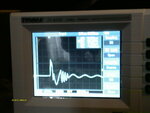
Please can you help in explaining the 53 Amp peak current spike (at the switching frequency) that I am seeing on the scope?
The duration of the spike is 1 microsecond.
The spike is seen in a 13 milliOhm current sense resistor in series with the sepic capacitor.
The ‘sense resistor’ is three 39 milliohm 1812 resistors in parallel.
So, to elaborate, I have put a 13 milliOhm sense resistor in series with the sepic capacitor and am seeing a strange spike across this sense resistor at the switching frequency. The spike is 700mV peak, indicating a current peak of 53Amps. Its duration is approximately 1us. I am thinking this must be a scope lead artefact as surely the current cannot be this high?…..i used a high frequency scope probing technique, and not the normal scope tip and ground lead.
The duration of the 53 Amp current spike is one microsecond.
My scope is a Tenma 72-8225:
https://www.farnell.com/datasheets/1661870.pdf
At maximum load power, the SEPIC inductor is warm to the touch, but not so warm that I can’t keep my finger on it all the time when running at room temperature….so I can’t understand how there can be a 53 Amp current spike in the sepic ?
Also, I’ve left this sepic converter running at 5W power continuously at room temperature for 24hrs, and it runs fine over all that time
I was suspecting that there might be ringing between the sepic inductor’s leakage inductance and the sepic inductor’s interwinding capacitance?…following the 53Amp current spike, there does seem to be a decaying ring at a frequency of approximately 500KHz ……I am also not sure if this 500KHz ring is real or a scope artefact?
V(in) is fixed at any level between 4V and 8V.
V(out) is any of several LED lamps , which could have voltages from 5V to 80V.
Off time is set to 3.88us.
Frequency of operation varies depending on load power and voltage, but is between 33KHz and 137KHz.
The ceramic sepic capacitor is 22uF , 1812 size.
The input and output capacitors are all ceramic.
The Coupled Sepic inductor is MSD1583-47uH :
**broken link removed**
The scope probe ground is one of those little metal protrusions which coils around the scope probe’s ground piece, and looks like a spring (for high frequency measurement)
When I touch the scope probe ground to the switching node of the sepic converter, I can see tiny little sparks as the scope probe ground protrusion rubs along the metal of the switching node pad. Why are these sparks seen? Is it something to do with the power supply that’s powering the sepic? (I assume its an isolated PSU , but don’t know, as the spec doesn’t say…it’s a Maplin GW02C PSU)
Bench Power supply used to supply sepic: (Maplin GW02C)
**broken link removed**
Incidentally, the current spike is 53Amps when measured with the scope probe on 1:1 setting, but when the scope probe is on 10:1 setting, then the spike is seen to be of magnitude 87 Amps.
Adjusting the bandwidth setting of the scope does not affect the size of the current spike seen on the scope.
The scope probe is 60MHz “UT-P03” and came with the scope.
Sorry I cannot take a scope sot as the scope doesn’t recognise the USB stick.
So, do you know if this “current spike” could just be a scope artefact ? (the expected peak sepic inductor current is just 2Amps when the load is 80V and 5W). Also, do you know why I’m getting sparks at the scope’s ground terminal when touching the sepic’s switching node?
Also, what would be the best equipment to use to view the current waveform in the sepic capacitor?..(eg a differential probe?)
Also, if this ringing/spiking is real, how should I best snub it out?
I have just designed a 5W constant-off-time Coupled-Inductor-Sepic Converter. (LED driver) Schematic is attached.
Coupled Inductor Sepic schematic:
https://i40.tinypic.com/1zvtp8y.jpg
Please can you help in explaining the 53 Amp peak current spike (at the switching frequency) that I am seeing on the scope?
The duration of the spike is 1 microsecond.
The spike is seen in a 13 milliOhm current sense resistor in series with the sepic capacitor.
The ‘sense resistor’ is three 39 milliohm 1812 resistors in parallel.
So, to elaborate, I have put a 13 milliOhm sense resistor in series with the sepic capacitor and am seeing a strange spike across this sense resistor at the switching frequency. The spike is 700mV peak, indicating a current peak of 53Amps. Its duration is approximately 1us. I am thinking this must be a scope lead artefact as surely the current cannot be this high?…..i used a high frequency scope probing technique, and not the normal scope tip and ground lead.
The duration of the 53 Amp current spike is one microsecond.
My scope is a Tenma 72-8225:
https://www.farnell.com/datasheets/1661870.pdf
At maximum load power, the SEPIC inductor is warm to the touch, but not so warm that I can’t keep my finger on it all the time when running at room temperature….so I can’t understand how there can be a 53 Amp current spike in the sepic ?
Also, I’ve left this sepic converter running at 5W power continuously at room temperature for 24hrs, and it runs fine over all that time
I was suspecting that there might be ringing between the sepic inductor’s leakage inductance and the sepic inductor’s interwinding capacitance?…following the 53Amp current spike, there does seem to be a decaying ring at a frequency of approximately 500KHz ……I am also not sure if this 500KHz ring is real or a scope artefact?
V(in) is fixed at any level between 4V and 8V.
V(out) is any of several LED lamps , which could have voltages from 5V to 80V.
Off time is set to 3.88us.
Frequency of operation varies depending on load power and voltage, but is between 33KHz and 137KHz.
The ceramic sepic capacitor is 22uF , 1812 size.
The input and output capacitors are all ceramic.
The Coupled Sepic inductor is MSD1583-47uH :
**broken link removed**
The scope probe ground is one of those little metal protrusions which coils around the scope probe’s ground piece, and looks like a spring (for high frequency measurement)
When I touch the scope probe ground to the switching node of the sepic converter, I can see tiny little sparks as the scope probe ground protrusion rubs along the metal of the switching node pad. Why are these sparks seen? Is it something to do with the power supply that’s powering the sepic? (I assume its an isolated PSU , but don’t know, as the spec doesn’t say…it’s a Maplin GW02C PSU)
Bench Power supply used to supply sepic: (Maplin GW02C)
**broken link removed**
Incidentally, the current spike is 53Amps when measured with the scope probe on 1:1 setting, but when the scope probe is on 10:1 setting, then the spike is seen to be of magnitude 87 Amps.
Adjusting the bandwidth setting of the scope does not affect the size of the current spike seen on the scope.
The scope probe is 60MHz “UT-P03” and came with the scope.
Sorry I cannot take a scope sot as the scope doesn’t recognise the USB stick.
So, do you know if this “current spike” could just be a scope artefact ? (the expected peak sepic inductor current is just 2Amps when the load is 80V and 5W). Also, do you know why I’m getting sparks at the scope’s ground terminal when touching the sepic’s switching node?
Also, what would be the best equipment to use to view the current waveform in the sepic capacitor?..(eg a differential probe?)
Also, if this ringing/spiking is real, how should I best snub it out?