Continue to Site

Welcome to EDAboard.com

Welcome to our site! EDAboard.com is an international Electronics Discussion Forum focused on EDA software, circuits, schematics, books, theory, papers, asic, pld, 8051, DSP, Network, RF, Analog Design, PCB, Service Manuals... and a whole lot more! To participate you need to register. Registration is free. Click here to register now.

[SOLVED] Can we use 4N25 optocoupler by giving 9V AC input

Status
Not open for further replies.

Mrunal Ahirrao

Full Member level 2
Joined
Nov 26, 2012
Messages
133
Helped
2
Reputation
4
Reaction score
2
Trophy points
1,298
Location
India
Activity points
2,213
Hi all,
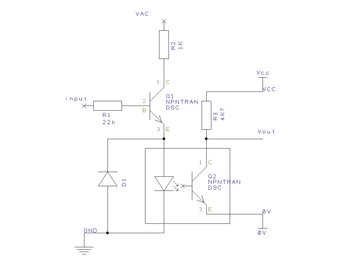
I am actually using circuit provided on https://www.circuitstoday.com/simple-water-level-idicator and wanted to interface the water level interface with a microcontroller. This is the circuit I am using simple-water-level-indicator.jpg. My question is can I interface the o/p on the transistors in circuit with 4N25 to interface it with Microcontroller. So how that can be done? Because input AC and output DC. Any help would be appreciated. Thankyou.
 

How about replacing the LEDs D1 to D5 with opto LED? You can keep the output gnd isolated from the sensor gnd.
R1 to R5 can be selected to match the opto LED drive current.

The outputs will pulse at 50Hz, but the software can be made to handle this.
 

How about replacing the LEDs D1 to D5 with opto LED? You can keep the output gnd isolated from the sensor gnd.
R1 to R5 can be selected to match the opto LED drive current.

The outputs will pulse at 50Hz, but the software can be made to handle this.

Thanks pinout for help. can't we use optocoupler? as handling a 1/0 is quite easy. I have tried using optocoupler, but it didn't worked. the current I hope was low at the input of 4N25. so the phototransistor in 4N25 did't ON fully so I didn't got full o/p. For handling this situation i have TIP122 darlington NPN transistor instead of given in circuit but don't know why it just didn't worked!
 

You also have to be mindful of the REVERSE voltage on the opto's LED input - the 4n25, like many optocouplers, has ABSOLUTE MAX reverse voltage of 5V. These devices will tolerate a volt or two of reverse voltage but I hae found that getting near or above their MAX ratings they will begin to fail, sometimes rapidly, sometimes intermittently. So, your design must ensure that if the opto's input cathode is at system ground, that the anode doesn't drop below ground ground by more than a diode drop or so (preferably 0V).
 
  • Like
Reactions: pinout

    pinout

    Points: 2
    Helpful Answer Positive Rating
Here is my suggested circuit.
I would select a different transistor from the darlington power transistor as it has high gain at high currents, but not at the mA collector current level.
The 2N2222 or others suggested in the original article would be much better.

At 9VAC I would have the collector load at 1K. 9V will be approx +/-12.5V so this will give an opto led current of around 10mA which is the nominal current level.
The diode D1 is added as per ftsolutions comment above.

Here is the basic circuit


Status
Not open for further replies.

Part and Inventory Search

Welcome to EDABoard.com

Sponsor

Back
Top