Continue to Site

Welcome to EDAboard.com

Welcome to our site! EDAboard.com is an international Electronics Discussion Forum focused on EDA software, circuits, schematics, books, theory, papers, asic, pld, 8051, DSP, Network, RF, Analog Design, PCB, Service Manuals... and a whole lot more! To participate you need to register. Registration is free. Click here to register now.

[SOLVED] Micro-Controller based multi-channel Remote controlled fan regulator

Status
Not open for further replies.
What happen if someone else use his TV remote and start playing with yours fans?
I assumed that the OP has no Sony TV in the same, or nearby room already. But would have been a good idea to check, admittedly.

If the Op does have a Sony TV in the same room, then simply change Sony address from 1 (TV) to 2 (VCR), assuming that nobody has a VCR any more.

... else there are these:

sony 01 tv address=01
sony 02 vcr1 addrsss=02
sony 03 vcr2 addrsss=03
sony 04 radio/cd addrsss=04
sony 06 laser disc/mdp addrsss=06
sony 06 vcr4 addrsss=07
sony 0b vcr3 address=0b
sony 0c surround sound address=0c
sony 0d tuner address=0d
sony 10 amp address=10 (cassette / tuner)
sony 11 cd player address=11
sony 12 equaliser address=12
sony 17 satellite STB address=17
sony 1a dvd address=1a

...whatever a universal remote will send...

Why does that code look familiar ? .... ... hmm I know! It's because I wrote it and put it on Libstock :lol::lol::lol:

Original is here: http://www.libstock.com/projects/view/43/infrared-tx-rx-samsung-sharp-nec-sony-rc5-rc6-toshiba-ir-easypic7-pic12-mmb18-mmb33-arm

...though I see that the shadow register is no longer used for avoiding RMW effects
 
Last edited:
  • Like
Reactions: tpetar

    tpetar

    Points: 2
    Helpful Answer Positive Rating
ya, thats a problem. Because SONY remote use SIRC protocol. that is used by many remote too.


The first problem is solved, but the second tusk is to regulate the fan speed.
 

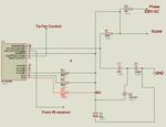
Yes, I'm using TRIACs. here is the connection diagram:
rxx.png

Its a ready circuit. But I still don't know why RC3-RC5 are pulled up. Also this circuit is getting a zero -crossing signal just like a square wave of 50% duty cycle.

Then how can I regulate?
 

Attachments

  • rxx.png
    rxx.png
    19.6 KB · Views: 111

I've make a code for fan regulation. But the problem is the pulses that is controlling the fan speed is not fixed and smooth. Fan speed is changing and fan is making a Ghttt!! Ghttt!! sound and then stops.


what is the fault of my code? Need help.
Code:
#define fan   RC0_bit
#define lamp1 RC1_bit
#define lamp2 RC2_bit


sbit ir_rx at RA2_bit;                  // IR receiver 40KHz
sbit ir_in_direction at TRISA2_bit;         // Infrared receiver input
// function prototypes
void get_mark_time(void);               // get Sony IR mark time

// global variables
char counter = 0;
char shadow = 0;
char bitcount;
char ir_address;
char ir_command;
int mark_time;
int fan_mask;
unsigned int num,Cnt_T1;


void interrupt()
{
    while(TMR0IF_bit)// TMR0 interrupt sub routine
    {
        counter++;                       // increment counter
        TMR0IF_bit = 0;                 // Clear Timer0 overflow interrupt flag
        break;
    }
    while(TMR1IF_bit)
    {
       TMR1IF_bit = 0;
       TMR1H = 0xFE;
       TMR1L = 0xE9; // 1ms count
       RAIE_bit = 0;//disable IOC interrupt
       if(!fan_mask)
       {
          // code
         Cnt_T1++;
         T0IE_bit = 0; // Timer0 interrupt ebable
         while(Cnt_T1 >= 0 && Cnt_T1 < num)
         {
          fan = 1;
          break;
         }
         while(Cnt_T1 >= num && Cnt_T1 <= 28)
         {
          fan = 0;
          break;
         }
          while(Cnt_T1>28)
          {
           fan = 1;
           TMR1IE_bit = 0; // disable timer1 interrupt
           RAIE_bit = 1;//Enable IOC interrupt
           T0IE_bit = 1; // Timer0 interrupt ebable
           break;
          }
       }
       else
       {
        fan = 1;
       }
     break;
    }

      while(RAIF_bit)// IOC subroutine
      {
       RAIF_bit = 0;// clear IOC_Flag
       TMR1IE_bit = 1; // enable timer1 interrupt
       Cnt_T1 = 0;
       break;
      }


}// interrupt

void GetData()
{
  ir_command = 0;                                        // initialise to prevent false trigger
  ir_address = 0;                                        // initialise to prevent false trigger
  get_mark_time();                                       // get Sony leader - 2.4mS Mark, 1.2mS space
  if ((mark_time > 120) && (mark_time < 200))  // set the frequency limit
  {         // ignore anything but 2.4mS mark

       for(bitcount = 0 ; bitcount < 7 ; bitcount++)
       {    // 7 bit command
          get_mark_time();                               // get a Sony IR bit
          ir_command >>= 1;                              // shift
          ir_command &= 0x7f;                            // top bit zero
          if (mark_time > 0x40)
          {                         // > 40 is assumed to be a 1
              ir_command ^= 0x80;                        // top bit 1
          }
      }
      ir_command >>= 1;                                  // shift 1 unused bit
      ir_command &= 0x7F;                                // clear top bit

      for(bitcount = 0 ; bitcount < 5 ; bitcount++)
      {     // 5 bit address
          get_mark_time();                               // get a Sony IR bit
          ir_address >>= 1;                              // shift
          ir_address &= 0x7f;                            // top bit zero
          if (mark_time > 0x40)
          {
              ir_address ^= 0x80;                        // top bit 1
          }
      }
      ir_address >>= 3;                                  // shift 3 unused bits
      ir_address &= 0x1F;                                // clear top 3 bits
  }
}// GetData


void main()
{
 TRISA = 0b00000111;
 TRISC = 0x00;
 PORTC = 0x00;
 ANSEL = 0x00;
 CMCON = 0x07;
 OPTION_REG = 0x03;            // TMR0 prescaler set to 1:16
 // start timer 0 counting
 GIE_bit = 1; // Global interrupt enable
 T0IE_bit = 1; // Timer0 interrupt ebable
 ir_in_direction = 1;// set IR dirrecting
 IOCA1_bit = 1; // Enable IOC at RA2
 RAIE_bit = 1; // Enable IOC interrupt
 RAIF_bit = 0; // Clear RAIF bit

 // Timer1 settings
  T1CON = 0x01;
  TMR1IF_bit = 0;
  TMR1H = 0xFE;
  TMR1L = 0xE9; // 1ms count // 1ms count
  TMR1IE_bit = 1;
  PEIE_bit = 1;
  Delay_ms(500);
  while(1)
  {

      GetData();
      num = EEPROM_Read(5);
      Delay_ms(20);
      if(ir_address == 1)
      {                                   // TV
          if(ir_command == 0)
          {                               // button 1
              num = 24;
              fan_mask=0;
          }
          if(ir_command == 1)
          {                               // button 2
            num = 22;
            fan_mask=0;
          }
          if(ir_command == 2)
          {                               // button 3
              //shadow ^= 0x10;                                // toggle output 4
              num = 20;
              fan_mask=0;
          }
          if(ir_command == 3)
          {                               // button 3
              //shadow ^= 0x10;                                // toggle output 4
              num = 18;
              fan_mask=0;
          }
          if(ir_command == 4)
          {                               // button 3
              //shadow ^= 0x10;                                // toggle output 4
              num = 15;
              fan_mask=0;
          }
          if(ir_command == 5)
          {                               // button 3
              //shadow ^= 0x10;                                // toggle output 4
              num = 12;
              fan_mask=0;
          }
          if(ir_command == 6)
          {                               // button 3
              //shadow ^= 0x10;                                // toggle output 4
              num = 9;
              fan_mask=0;
          }
          if(ir_command == 7)
          {                               // button 3
              //shadow ^= 0x10;                                // toggle output 4
              num = 4;
              fan_mask=0;
          }
          if(ir_command == 8)
          {                               // button 3
              //shadow ^= 0x10;                                // toggle output 4
              num = 0;
              fan_mask=0;
          }
          if(ir_command == 9)
          {                               // button 0
              //shadow = 0x00;                                 // all outputs off
             fan_mask=1;
             num = 0;
          }
          EEPROM_Write(5,num);
          Delay_ms(200);
          num = EEPROM_Read(5);
          Delay_ms(100);
      }

  }
}

// get time of mark, then ignore space
void get_mark_time(void)
{
    while(ir_rx);                           // wait for a mark
    counter=0;
    TMR0 = 0;
    while(!ir_rx);                          // wait for space
    mark_time = (counter << 8) + TMR0;      // collect integer mark time

}
 
  • Like
Reactions: PA3040

    PA3040

    Points: 2
    Helpful Answer Positive Rating
Dear Mithun_K_Das,


Can u please upload the schematic and HEX code for the remote control using 12f675.


Thanks
 

Dear All,
How should we detect the start bit using Timer0 in assembly language with pic16f877a
Thanks in advance
 

Dear All,
How should we detect the start bit using Timer0 in assembly language with pic16f877a
Thanks in advance


Try to find the zero crossing first, then calculate from that point.
 
  • Like
Reactions: PA3040

    PA3040

    Points: 2
    Helpful Answer Positive Rating
Status
Not open for further replies.

Similar threads

Part and Inventory Search

Welcome to EDABoard.com

Sponsor

Back
Top