Continue to Site

Welcome to EDAboard.com

Welcome to our site! EDAboard.com is an international Electronics Discussion Forum focused on EDA software, circuits, schematics, books, theory, papers, asic, pld, 8051, DSP, Network, RF, Analog Design, PCB, Service Manuals... and a whole lot more! To participate you need to register. Registration is free. Click here to register now.

isolated IGBT Trigger -DC chopper

Status
Not open for further replies.

saraaj100

Junior Member level 1
Joined
Sep 24, 2010
Messages
18
Helped
0
Reputation
0
Reaction score
0
Trophy points
1,281
Location
Chennai, India
Activity points
1,406
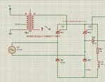
Hello...I want to chop the DC so that 585VDC into 400VDC. I dont know How to Connect the gate of IGBT w.r.t Emitter. Because Emitter here is not at zero or Grounded, Its floating. The ground of Microcontroller connection should NOT be mixed with the high voltage section.

Suggest me a circuit to Trigger the IGBT in this configuration. Triggering may be used with pulse transformer or GATE DRIVER from ST like L6390 or IR21XX or Opto-Coupler. I need a isolated Triggering from Microcontroller.
IGBT GATE TRIGGER.png

Is it possible or not. Help me with a Gate trigger circuit.
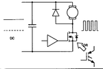
 

You need an isolated power supply for the gate driver and a suitable driver circuit. An opto-isolated gate driver like TLP250 would be fine.

Your schematic doesn't show a valid chopper circuit. A buck converter must use a suitable inductor and a fast rectifier diode.
 

IGBT control must be applied between gate and emitter not collector; there are a lot of isolated drivers able to do such job.
 

IGBT control must be applied between gate and emitter not collector; there are a lot of isolated drivers able to do such job.


Can you suggest a circuit diagram with exact connection. Whatever Optocoupler circuit i tried. the emitter will be in floating condition or the ground of microcontroller will be connected to high voltage ground. So kindly show some circuit.
Thanks for the reply.
 

Yes, the emitter is floating, so there must be a floating (isolated) power supply of 12 to 15 V, or ultimately a bipolar supply (e.g. +/- 12) to provide a negative gate voltage. Connect a TLP250 or similar and you're done.
 

Yes, the emitter is floating, so there must be a floating (isolated) power supply of 12 to 15 V, or ultimately a bipolar supply (e.g. +/- 12) to provide a negative gate voltage. Connect a TLP250 or similar and you're done.

Where i am done... I didn't connect any external +/- Power supply say 'A' to the Emitter.. How it can be done...When i connect power supply 'A' lower potential voltage(say ground or negative) to the emitter of IGBT, the high power Voltage from the rectifer will fall or flow via power supply 'A' lower potential.
 

I'm not sure if you understand what an isolated power supply is?
 

By moving IGBT as emitter be tied to negative point of power supply, you may avoid an auxiliary power supply; need a transistor and few resistor and use same power supply.
 

Attachments

  • 30229.gif
    30229.gif
    3.6 KB · Views: 91
  • Like
Reactions: FvM

    FvM

    Points: 2
    Helpful Answer Positive Rating
By moving IGBT as emitter be tied to negative point of power supply, you may avoid an auxiliary power supply; need a transistor and few resistor and use same power supply.

You tied Negative point of power supply simply to Emitter of IGBT. So ground referencing is not complicated. What i am saying is the emitter is not connected to ground rather it is connected to another 6 pulse inverter circuit. Problem is still not solved:shock::oops:

- - - Updated - - -

Yes ...Sorry I couldnt understand the point of isolated extra power supply
 

Saraj100:
I don't want to discourage you from learning power electronics, but why don't you start learning power electronics at a much safer level, let's say 12V?

I'm saying this because by the level of your questions, it is apparent that you have never worked with high power circuits before.

I used to design DC power controllers for a living. I can tell you from personal experience that 585 V DC is an extremely dangerous voltage. The problem with DC, once that one reaches a level of about 40 volts, is that it is not easily interrupted. You make a mistake, and very quickly you have an out of control arcing that starts a fire. That in addition that at that voltage, electrocution is assured.
A technician of mine -and he was an experienced technician- was blinded in one eye when a large diode exploded during an overload condition.
Another engineer burned his hand and destroyed an oscilloscope during an arcover.
I still have ringing in one ear caused by a full bridge explosion.

I have had more than one engineer quit after an accident, not because they had suffered bodily harm, but because they were to scared to power it up again.

Again, don't take this as a putdown. But let me assure you that power electronics IS NOT like say, digital circuits, whereas you make a mistake, you correct it easily. A mistake in power electronics means hundreds (if not thousands) of dollars in damages, and perhaps a permanent injury to yourself or someone else.
 

Sorry I couldnt understand the point of isolated extra power supply
It means you have an extra transformer winding with sufficient insulation strength or an isolated DC/DC converter to supply the gate driver circuit.
 

It means you have an extra transformer winding with sufficient insulation strength or an isolated DC/DC converter to supply the gate driver circuit.

Ok..If i connect the DC-DC converter or isolation transformer...Where should i connect the return path of secondary winding?? dc-dc converter.pngdc-dc converter.png.

- - - Updated - - -

I frightened from your experience... Thank you very much for your sincere and caring advice ..

I also had a similar happening a week before...When i connect neutral of AC line to the DC Ground..A burst in breadboard..Heavy spark its like lightening at sky..smoke came.. Breadboard and components melted. It all happens in second. The big thing in it is, Distribution transformer has broken its fuse..Thank *** i used safety glass and gloves.

Keep your advice in mind and learn it safely...One problem is everything works fine in simulation ..When going in hardware the problem starts..
Thank you schmitt trigger


Saraj100:
I don't want to discourage you from learning power electronics, but why don't you start learning power electronics at a much safer level, let's say 12V?

I'm saying this because by the level of your questions, it is apparent that you have never worked with high power circuits before.

I used to design DC power controllers for a living. I can tell you from personal experience that 585 V DC is an extremely dangerous voltage. The problem with DC, once that one reaches a level of about 40 volts, is that it is not easily interrupted. You make a mistake, and very quickly you have an out of control arcing that starts a fire. That in addition that at that voltage, electrocution is assured.
A technician of mine -and he was an experienced technician- was blinded in one eye when a large diode exploded during an overload condition.
Another engineer burned his hand and destroyed an oscilloscope during an arcover.
I still have ringing in one ear caused by a full bridge explosion.

I have had more than one engineer quit after an accident, not because they had suffered bodily harm, but because they were to scared to power it up again.

Again, don't take this as a putdown. But let me assure you that power electronics IS NOT like say, digital circuits, whereas you make a mistake, you correct it easily. A mistake in power electronics means hundreds (if not thousands) of dollars in damages, and perhaps a permanent injury to yourself or someone else.
 

The DC/DC converter was meaned to supply a gate driver circuit, not to feed the gate with a DC voltage. We would model it with a floating DC voltage source, not a transformer.

A thyristor can be triggered by pulses transmitted through a trigger transformer, without active components on the secondary side, but that's a different story.

For IGBT gate control, we have to stay with a gate driver circuit that can source and sink multiple amperes. Said TLP250 would be a simple single chip solution, but there are advanced IGBT drivers with overcurrent sensing and other features available if you need it. In any case, an isloated power supply is required.

For bridge output stages with smaller IGBTs, integrated bootstrap drivers like IR2110 can be used, but they don't work for a one-transistor chopper.
 

Here you are speaking about many things, 1. DC/DC converter 2. Trigger pulse transformer 3. TLP250 IC 4.Bootstrap Driver ICs...I couldnot get any clear idea to solve the problem i stated,
On your words, ONE-TRANSISTOR CHOPPER I need a solution for this , Why dont you show any circuit idea rather than words....Thanks
 
Last edited:

Status
Not open for further replies.

Similar threads

Part and Inventory Search

Welcome to EDABoard.com

Sponsor

Back
Top