Continue to Site

Welcome to EDAboard.com

Welcome to our site! EDAboard.com is an international Electronics Discussion Forum focused on EDA software, circuits, schematics, books, theory, papers, asic, pld, 8051, DSP, Network, RF, Analog Design, PCB, Service Manuals... and a whole lot more! To participate you need to register. Registration is free. Click here to register now.

Using a transistor to enable/disable power to IC's

Status
Not open for further replies.

Lloyd Atkinson

Newbie level 3
Joined
Feb 10, 2013
Messages
4
Helped
0
Reputation
0
Reaction score
0
Trophy points
1,281
Activity points
1,327
Hi,

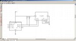
I'm making a small battery powered temperature logger, so I'm trying to create a circuit that will make sure the battery life last's for as long as I can make it do so. I've come up with the idea of the microcontroller I'm using in the design to be able to use a transistor to be able to turn the other chips on in the circuit when it needs to use them and then turn them off again once it's finished talking to them. So far the only chips in the design is the uC and an I2C EEPROM.

Will this design I've created work? Also, are there any changes I should make to it? I believe a BC547B will be suitable? I've attached a circuit diagram to demonstrate what I'm asking.

Thanks for any help! :)

untitled.JPG
 

Attachments

  • untitled.JPG
    untitled.JPG
    229.1 KB · Views: 216

One option can be usage of P-MosFET.

How you get 5V? You can use voltage regulator with shutdown option.
 

Not sure what your battery supply is, but if it were 2 x CR2032 coin cells, then you'd have 400mAh of juice. The 24AA1026 consumes 5uA stand-by current. If it were just sitting in standby alone on these cells, it would take 80,000h for this IC to deplete them, which is just over 9 years.

The PIC in stand-by mode looks like 1nA @ 2V, which is too insignificant to consider.

While the EEPROM is writing, it comsumes 5mA (1000 times the standby current). The BC547B has a gain of about 200, so you will need an extra 5000/200 = 25uA into the base while the EEPROM is writing.

Considering that you are probably writing on a very short duty cycle, I think it would probably work for extending battery life if you really need extremely long life (10+ years).
 

Both the MCU and EEPROM look like they can run at 2V. They will probably consume less power at a lower voltage.
 

Hi,

Thanks for the replies, they have been very useful.

"While the EEPROM is writing, it comsumes 5mA (1000 times the standby current). The BC547B has a gain of about 200, so you will need an extra 5000/200 = 25uA into the base while the EEPROM is writing."

Can you explain this a little, do you mean the BC547 wouldn't be suitable?

Also, as for the MOSFET idea, the BC547 I believe can supply up to 500 mA, and the EEPROM dosen't consume this amount, so why would I need to use a MOSFET? I'm still learning, you'll have to forgive me!

Thanks
 

PIC12F675 have 2-5,5V voltage range as Centmo earlier mention, maybe consider usage on 3V. Also 24AA1026 have voltage range from 1,7V to 5,5V and have read current of 450uA and standby 5uA.
 

I think the BC547 is fine, I was just trying to account for all the current consumed in the circuit, since it adds another 1/200 = 0.5% to the current consumed by the EEPROM on the NPN base. It will also consume power in the form of a voltage drop, Vce in the saturation mode (0.25V max).

The MOSFET, on the other hand, will consume practically nothing on the gate, and will drop the voltage less across Vds. For example, with Rds(on) = 5ohm, and I = 5mA, Vds = 0.025V. This lends itself better to operating at a lower voltage.

I agree, I'd go with 3V power supply. So, in my CR2032 example, you'd connect the two cells in parallel instead of in series. Those cells will provide pretty much all their power above 2V.
 
There are plenty of "power strobe" or supply switches out
there for such uses, with clean digital input and no discrete
components.
 

A transistor used as a switch has a low saturation voltage drop of only 0.05V when its current is only 5mA.
But your NPN transistor is not a saturated switch, instead it is an emitter-follower with a voltage drop of 0.7V to 0.8V. Its series base resistor R3 is not needed and is causing an even higher voltage drop.
 
Following on from what Audioguru said....
It would be better to replace the BC547 in your circuit with a BC557 PNP transistor, with the emitter and collector connections swapped around. That will give you a saturating switch with little voltage drop. It will switch on when GP5 is low - the opposite of the original circuit.
 
With a PNP transistor you definitely do need the base resistor to limit the base current.
 

I looked into MOSFETs for this purpose, but the package type you've chosen (through-hole) and low gate Vgs requirement (circuit needs to run down to 2V) really cuts down the suitable parts. I think the BC557 as godfreyl suggested is a good choice.
 
Last edited:

Yes I looked at MOSFETS online (I've not used them much yet) and I couldn't find any that were suitable for low voltages like this, but then again I may not have been searching with the right keywords.

What value would be suggested for the base resistor to the PNP? Also, what calculation is used to get the value?

Thanks
 

On its datasheet, the BC557 guarantees saturation when its based current is 1/20th its collector current. Somebody says that your load is only 5mA and you want it to work when the supply is only 2V so the current in the resistor is 5mA/20= 0.25mA and the voltage across the resistor is 2V - 0.7V= 1.3V.
Then the resistance is 1.3V/0.25mA= 5.2k ohms. Use 5.1k which is a standard value.
 
Last edited:
If you are relying on the watchdog timer to wake up the microcontroller you might want to look at the LF microcontrollers (XLP) to minimise current.

Keith
 

TI is also an industry leader in ultra low-power MCUs.

MSP430FR5969 Wolverine
 

Status
Not open for further replies.

Part and Inventory Search

Welcome to EDABoard.com

Sponsor

Back
Top