Continue to Site

Welcome to EDAboard.com

Welcome to our site! EDAboard.com is an international Electronics Discussion Forum focused on EDA software, circuits, schematics, books, theory, papers, asic, pld, 8051, DSP, Network, RF, Analog Design, PCB, Service Manuals... and a whole lot more! To participate you need to register. Registration is free. Click here to register now.

[SOLVED] How to drive common cathod large 2.3" 7 segement display pic mcu

Status
Not open for further replies.

asking

Full Member level 5
Joined
Sep 21, 2010
Messages
279
Helped
6
Reputation
12
Reaction score
6
Trophy points
1,298
Activity points
3,377
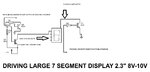
I need help driving large 7- Segment display 2.3" 8-10Volt to operate. I made such circuit and tried to run but it always shows flickering and 8888 in the display can anyone tell me whats the reason behind this ? I have tested before using fast blinking source and all displays were blinking perfect. But when i use for multiplexing its not working. There's seems to be some error or delay...i donno why... i cannot use ULN2803 Because i have common cathod display i need positive source driver like UDN2981 but i dont have that so i designed this transistor switching circuit...but i doubt that its not working with MCU duty cycle and hence its not showing proper data...can anyone tell me...is my doubt right ? or something leakage current ?

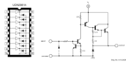
The circuit i designed is attached. SOURCE DRIVER CIRCUIT.jpg
 

First, it looks like you don't have any current limiting resistor in your anode drive. Are there internal resistors in the display? if not, you'd better add them or you'll destroy your display. You should probably have a resistor in the base of Q8 as well. Have you verified (with a scope) that your segments are being fully turned on and off? The circuit looks fundamentally correct, (other than being upside down.) I think you need to get in there with a scope.
 
  • Like
Reactions: asking

    asking

    Points: 2
    Helpful Answer Positive Rating
First, it looks like you don't have any current limiting resistor in your anode drive. Are there internal resistors in the display? if not, you'd better add them or you'll destroy your display. You should probably have a resistor in the base of Q8 as well. Have you verified (with a scope) that your segments are being fully turned on and off? The circuit looks fundamentally correct, (other than being upside down.) I think you need to get in there with a scope.

Yes, I tried to turn off and on @ 500ms using some test program....at that time it was working...but when it comes to multiplexing, its over. Btw...not adding any resistor will cause time delay ? Because my displays are fine working without Resistor. Although i will apply 10 Ohm Resistor...as recommended. Do you think any current is reveresed to microcontroller ? during this process ?
 

If it works fine with no resistor, then there probably are internal resistors in the display. No, the resistors won't add any delay.

What exactly do you mean by "turn off and on @500ms"? Was the the cathode pulled low and you were turning the segments on and off? Were you driving the cathode on and off?

What are you expecting to see? Are you driving 4 displays? Are you driving the same number onto each digit? Are you sure the cathode drive is synchronized with the digit-data?

What i mean to say is.... I m successful while driving Common Cathod Displays. Means common cathod pins...using BC547 or any other NPN Transistor. Only thing which matters is the Data line for A B C D E F G of 7 segment display. I searched google and found that people always use ULN2803 for it and not individual transistor drivers. But my case is common cathod so i need common anode driver like UDN2981. i have ordered it and m waiting now. Because its easy to driver Selection of 4 Common cathod display but to control the Data line we required Source Driver like UDN2981. So lets give a try using source driver circuit....i hope you got me...
 

What?

First you say you are having trouble driving a common-cathode display (post #1) and then you say "I'm successful driving Common Cathode Displays". (post #6).

Did you put a resistor in the base of Q8? HAVE YOU LOOKED AT YOUR SIGNALS WITH A SCOPE?

And people don't "Always use ULN2803".
 
  • Like
Reactions: asking

    asking

    Points: 2
    Helpful Answer Positive Rating
What?

First you say you are having trouble driving a common-cathode display (post #1) and then you say "I'm successful driving Common Cathode Displays". (post #6).

Did you put a resistor in the base of Q8? HAVE YOU LOOKED AT YOUR SIGNALS WITH A SCOPE?

And people don't "Always use ULN2803".


Sorry for my mistyped... English...

"What i mean to say is.... I m successful while driving Common Cathod Displays. Means common cathod pins...using BC547 or any other NPN Transistor. "

I mean to say people mostly use ULN2803, Because they have common anode displays, Mean their Data pins for 7 Segment Display are +ve (anodes).

I have updated the Image with arrows...please if you can understand. And yes i had Resistor in the base of Q8, but no change....

Again m sorry for my bad English above as i was in hurry :p
 

Attachments

  • SOURCE DRIVER CIRCUIT.jpg
    SOURCE DRIVER CIRCUIT.jpg
    70.2 KB · Views: 196

Your schematic looks functionally correct. You need to measure some points in your circuit to make sure things are turning on and off like you think they should.
 

Your schematic looks functionally correct. You need to measure some points in your circuit to make sure things are turning on and off like you think they should.

Yes, Actually i tried everything......but @ high speed 4ms (multiplexing) everything gets messed up... :p so i think UDN2981 will solve problem for data pins. :D just waiting for it to arrive. 24 hours left :p if you have any suggestion please do lemme know..about this circuit...
 

Are you SURE your software is not the problem? Did you try slowing down your scan rate as a test?
 

Re: How to drive common cathod large 2.3" 7 segement display pic mcu

Are you SURE your software is not the problem? Did you try slowing down your scan rate as a test?

Barry,

I have connected small display parallel already and they're fine (just for checking). Only the problem with big display is to drive them properly with proper driver circuit. I m getting 8 8 8 8 on big four displays....so i dont think that's software issue.

- - - Updated - - -

While Reading UDN2981 Datasheet i found this circuit for the its internal structure and i think its different than what i designed. So waiting for that to try. check the attached UDN2981 Internal circuit.
 

Attachments

  • udn2981.png
    udn2981.png
    16.5 KB · Views: 266

You've got me confused. Have you EVER had this display working? Your original post said "all displays were blinking perfect". Please select one of the following:

1) You tested a different display with a different circuit, and that worked.
2) You tested this display with a different circuit, and it worked.
3) You tested a different display with this circuit, and it worked.
 
  • Like
Reactions: asking

    asking

    Points: 2
    Helpful Answer Positive Rating
asking, bro
just tell barry that you have tried common-cathode 7segment displays (small - ones) which perfectly showing time given by RTC, but the problem is PIC / 8051 works with 5V circuit and operates at 5v interfaces with it, now you have to drive 12V Common Cathode Display (bigger one) so problem is that this bigger displays not working while showing 8888...

so better to find some driving circuit that works at this fast rate with synchronization with the rate of PIC / 8051 data rates, the main problem is u have to convert all the ABCDEFGH signals as well as 4 - Digit Selection Pin Logic to 12V at the rate of controller gives output to 7 segment display, so lack of synchronization comes and gives u the 8888 output becoz at this rate driver circuit cannot achieve the timing sync with data selection....

in simple way u have to convert all the 5V signals to 12V signals at the same rate that provided by PIC / 8051.... synchronization matters...
 
  • Like
Reactions: asking

    asking

    Points: 2
    Helpful Answer Positive Rating
Re: How to drive common cathod large 2.3" 7 segement display pic mcu

You've got me confused. Have you EVER had this display working? Your original post said "all displays were blinking perfect". Please select one of the following:

1) You tested a different display with a different circuit, and that worked.
2) You tested this display with a different circuit, and it worked.
3) You tested a different display with this circuit, and it worked.

Barry,

As manthan said,

We have been trying to Drive 8-10V Display using microcontroller signals. We are not successful. While the same i checked with small display on Development board its working fine. Means there's no any programming issue. Only thing is we need to convert the 5V logic output state to 8-10V to drive the displays :D i hope you're doubts are cleared.

- - - Updated - - -

As you said...i just checked big displays just by applying simple on/off signal to their inputs circuit and it worked. So i thought it would be work too with high speed but problem comes here, when we multiplex the display.
 

At the risk of repeating myself,

have you looked at your signals with an oscilloscope?

There's no reason this shouldn't work, unless you don't have your circuit right.
 

At the risk of repeating myself,

have you looked at your signals with an oscilloscope?

There's no reason this shouldn't work, unless you don't have your circuit right.

Yeah i tried sometimes before signals for NPN Transistor seems to be fine but not for PNP Transistors...
 

okay....so, WHY DIDN'T YOU SAY SO????? Just repeatedly posting, 'it doesn't work' does not help resolve the problem.

What seems to be the problem? My guess is that the PNP is not turning off which would indicate that the two resistors on the the base are not proper values. The base should be pulled to within less than 0.6V of the +12 rail in order to insure that the PNP is off. When Q8 is off, it's collector should be close to 12 volts (no current should be flowing into the collector).

Just a thought, are you sure the transistors are connected correctly?
 
  • Like
Reactions: asking

    asking

    Points: 2
    Helpful Answer Positive Rating
okay....so, WHY DIDN'T YOU SAY SO????? Just repeatedly posting, 'it doesn't work' does not help resolve the problem.

What seems to be the problem? My guess is that the PNP is not turning off which would indicate that the two resistors on the the base are not proper values. The base should be pulled to within less than 0.6V of the +12 rail in order to insure that the PNP is off. When Q8 is off, it's collector should be close to 12 volts (no current should be flowing into the collector).

Just a thought, are you sure the transistors are connected correctly?

Dear barry,

Finally i connected UDN2981, Now display worked....But i think its Dim....might be duty cycle would be too high so currrent is averaged....yes...i think you're right...my transistor circuit was correct will have alook @ analysis why it did not worked... :D
 

If your duty cycle is 25%, your peak current needs to be 4 times nominal. In other words, if the display is specified to run at 20mA, you need to drive 80mA into it when it's active.
 
  • Like
Reactions: asking

    asking

    Points: 2
    Helpful Answer Positive Rating
Status
Not open for further replies.

Similar threads

Part and Inventory Search

Welcome to EDABoard.com

Sponsor

Back
Top