Continue to Site

Welcome to EDAboard.com

Welcome to our site! EDAboard.com is an international Electronics Discussion Forum focused on EDA software, circuits, schematics, books, theory, papers, asic, pld, 8051, DSP, Network, RF, Analog Design, PCB, Service Manuals... and a whole lot more! To participate you need to register. Registration is free. Click here to register now.

how to capture image using c3088 camera module

Status
Not open for further replies.

Robin Khosla

Member level 4
Joined
Aug 2, 2012
Messages
76
Helped
7
Reputation
14
Reaction score
6
Trophy points
1,298
Activity points
1,861
hii,


i have purchased c3088 camera module and want to interface it with fpga.
curently i am working on capturing black and white image from it ,but
i am unable to find out how will it capture image can anyone help??
 

thanks that was helpful

but how to capture the image ?

now i am clear with how the pixels will be brought in to memory but

when we click the button as in other cameras to capture image
similarly what we have to do here or what signal to be send to c3088 to capture image??


in your referred link they are storing 3rows in buffer each time but when will the the camera click image?
 

Depends what you want to do with the image data. Since the module apparently just sends data continuously, you might want to:

- Set aside some RAM (BRAM, or external RAM, depending on how large the image is)
- Configure the camera module as necessary
- Wait for the thing that indicates the module is sending a new image
- Read from the camera module. Dump the data into RAM
- Repeat until you determine that it's the end of the image frame.
- Stop, and then do something interesting with the image you now have in RAM.

The module doesn't have a button, so perhaps you want to capture one image when you push a button attached to your FPGA board? In that case, you will need to adjust that slightly to wait for the button to be pressed before you start waiting for the start of an image.
 

yes i want to capture an image when i press a button on Fpga,
before that i want to know about the c3088 registers which are to be configured as mentioned in Peter Fleury's code

https://people.ece.cornell.edu/land...Projects/s2009/dat38/Website/code/i2cmaster.h

1. what i need to do with i2c interface i.e. which registers are to be configured and how?
2. if i don't configure the camera through I2C interface, are their any default settings of camera with which the camera will work?
 

The datasheet might state what the power-on settings are. In general, I wouldn't count on the registers being correct and would always initialise them.

I2C is a fairly standard protocol and there are plenty of FPGA implementations of it around. Device datasheets usually state their own requirements for the bus. You might want to use a soft processor to make setting I2C registers easier.. but if there aren't many to set, you might get away without one.
 

i have checked the interfacing of c3088 with fpga without the i2c interface but it doesn't give any output
so it means i have to do some i2c programming for that..
but again the same problem i am facing is that

i know 0c0 is for write and 0c1 for read but on which address i have to send this data
e.g. i2c has some frame format
i.e start bit- address- rw- data - stop bit

but what address to use if i want to use data c1?
and how many bits of address?
 

thanks that was helpful


but where are the other functions
1. i2c_start
2. i2c_write
 

Did you look at farhada's first link? Toward the bottom of the page, it says:

"twimaster.c (6KB) – the I2C master library, written by Peter Fleury"

Note that it uses the Atmel AVR's I2C hardware, but implementing I2C on an FPGA is reasonably straightforward.
 
Check out for example Xilinx xapp333 for a useable i2c master implementation.
 

thanks


1. with what frequency the bits are to be transfered to c3088?
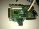
2. i have connected the 32 pins of c3088 directly to FPGA I/O port A2 leaving its 4 pins(out of 40) from both sides is it correct as shown in figure?
02112012409.jpg
 
Last edited:

1 - Have you read the OV6620 data sheet? Table 12 and 13? The pixel clock frequency will depend on the mode you're using.

2 - Is the module designed to be plugged into the Spartan 3 board like that? Don't assume that just because the connector fits that it will work. You must examine the pinout of the FPGA board's connector and the pinout of the camera module's connector. You MUST ensure that power and ground connections are in the correct locations, AND that the voltages are within the acceptable limits for the camera module. You also need to ensure that the FPGA's I/O pin electrical standards are compatible with that of the module.

Unless the module is specifically designed for the board (doesn't look like it), it is pretty unlikely that you can just connect them together like this without an adaptor of some sort.
 

1. pclk clock i am recieving from camera module so for that i am writing
if (pclk'event and pclk='1') then
so with this condition it will identify when pclk's events, i don't think that i have to generate the pclk frequency don't you think so???

2. i have connected the module to i/o pins of the board and giving vcc ,gnd through software in the ucf file. however, the vcc,gnd mentioned in the fpga's i/o connector are different. i have checked with multimeter the voltage across pin vcc which i am mentioning in ucf file, it is showing 3.6V, will it take it as '1' ??
 

1) I didn't really read the camera's datasheet thoroughly, but it sounds like it would generate the pixel clock for you.

2) Check the electrical ratings for the module - don't take my word for it! Don't exceed any absolute maximums on either the module or the FPGA or you will cause damage.

You can't just set an FPGA I/O pin to high or low and make it work as a VCC or GND for external peripherals. It might work, but these pins can only source a VERY LIMITED amount of current. Sourcing or sinking too much current WILL destroy the I/O pad. Connect your module's power directly to a power supply. I think the camera required 5V anyway. The Spartan-3 does not have 5V capable I/O, so this wouldn't work anyway.

Do you have someone local such as a supervisor or professor whom you can ask these sorts of questions? It'll be much quicker for you to work through with someone knowledgeable in person.
 

The thing is that the pixels are coming out of camera module and i am able to display them on led's but on lcd correct picture is not seen..
also if i capture the same image each time a different output is obtained...
i am unable to figure out where the error is...
the following code i am using to get pixels out...

if (cam_pclk'event and cam_pclk='1') then
if (cam_vsync='0') then
if (cam_href='1') then
if (hcnt = 356) then
hcnt := 0;
if (vcnt= 292) then
vcnt:= 0;
else
vcnt := vcnt + 1;
end if;
else
hcnt := hcnt + 1;
end if;

if (hcnt>8 and hcnt <= 136 and vcnt >24 and vcnt<=152) then
cam_o <= cam_y;
cam_led(7 downto 1) <= cam_y(7 downto 1);
end if;
end if;
end if;
end if;

the above logic i used to arrange the pixels in form of image.... vsync ,hsync and pclk are the timing signals and the maner in which pixels come out is shown in figure below:


the camera module is not interfaced by anyone near our area, that's why i am asking for help here...
 

I would suggest using signals rather than variables for the counters, although I doubt thats your problem.
Have you full simulated it?
 

It's not really clear to me how you're capturing the same picture each time.. even if you don't move the camera or subject, the picture won't be exactly the same every time due to changing light conditions or random noise. If you're able to see an output on an LCD, can you deduce anything from the 'incorrect' picture about what the problem might be?

Anyway, the thing that concerns me is that you don't have any way to synchronise the pixel counters. You should be looking for positive transitions of VSYNC and resetting HCNT and VCNT, and for positive transitions of HSYNC and resetting HCNT (if my understanding of your waveform diagram is correct). It's generally a bad idea to assume that everything will start in sync and stay in sync!
 

i think that's a close answer to my problem


well camera is in same position and it doesn't output same image each time but somewhat same


the thing is that i can't take the clk'event and clk='1' for all hsync,vsync and pclk, because these are connected to the i/o ports and they cant operate as clks. if i take them as clk then code synthesises but doesn't implement and gives the following error message:

ERROR:place:645 - A clock IOB clock component is not placed at an optimal clock
IOB site. The clock IOB component <pclk> is placed at site <IOB_X2Y24>. The
clock IO site can use the fast path between the IO and the Clock buffer/GCLK
if the IOB is placed in the master Clock IOB Site. If this sub optimal
condition is acceptable for this design, you may use the
CLOCK_DEDICATED_ROUTE constraint in the .ucf file to demote this message to a
WARNING and allow your design to continue. However, the use of this override
is highly discouraged as it may lead to very poor timing results. It is
recommended that this error condition be corrected in the design. A list of
all the COMP.PINs used in this clock placement rule is listed below. These
examples can be used directly in the .ucf file to override this clock rule.
< NET "pclk" CLOCK_DEDICATED_ROUTE = FALSE; >
ERROR:pack:1654 - The timing-driven placement phase encountered an error.


However, i took the pclk signal and put it in place where external crystal can be connected to resolve the above error and then pcl'event and pclk='1' works... and i am getting 8.86 Mhz from camera.
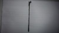
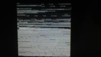
The picture captured from the camera and displayed on lcd is shown in figure below (right side) and the picture i tried to capture is also shown below (left side)...


it is difficult to deduce from the above picture where the error may be because i tried to capture the horizontal black line instead of vertical but obtained nearly similar output image
 

what format is the camera?
what format can the LCD accept?

if the two dont accept the same formats, the you will need to do a format conversion
 

Status
Not open for further replies.

Part and Inventory Search

Welcome to EDABoard.com

Sponsor

Back
Top