osa1313
Junior Member level 3
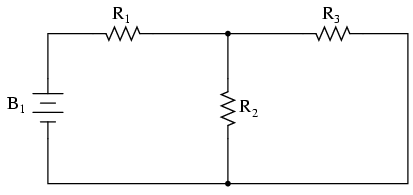
Hi i have been stuck on this circuit for a long time and it seems impossible how current labelled I4 on the circuit below is 4mA.
Maybe somebody is kind enough to explain this to me, i have searched 5 books and none of them do an example on more than 4 resistors connected in this way.
The image, you can enlarge it by clicking on it.

Thank You for any help as this will help me pass my GCSE Electronics without being able to attend to the class.
Maybe somebody is kind enough to explain this to me, i have searched 5 books and none of them do an example on more than 4 resistors connected in this way.
The image, you can enlarge it by clicking on it.
Thank You for any help as this will help me pass my GCSE Electronics without being able to attend to the class.
")