hamzahumayun
Newbie level 4
Hi,
While reading Microelectronics Circuits by Sedra Smith i had the following query
the formula we get for non inverting op amp is 1 + R2/R1, now to turn it into voltage follower it suggests that make R2= 0 and R1 = infinite, i was wondering if R2 = 0 is sufficient and we could keep R1 in the circuit and it should still be a voltage follower, would it work?
Regards,
Hamza
![Circuit1 - Multisim - [Circuit1 ]_2012-06-24_17-27-07.png](https://www.edaboard.com/data/attachments/21/21133-362f7552b2ac95d2c653f4dd4fa9368e.jpg "Circuit1 - Multisim - [Circuit1 ]_2012-06-24_17-27-07.png")
![Circuit1 - Multisim - [Circuit1 ]_2012-06-24_17-26-40.png](https://www.edaboard.com/data/attachments/21/21134-cf18f40a93026b12c7e98e10c9297c1d.jpg "Circuit1 - Multisim - [Circuit1 ]_2012-06-24_17-26-40.png")
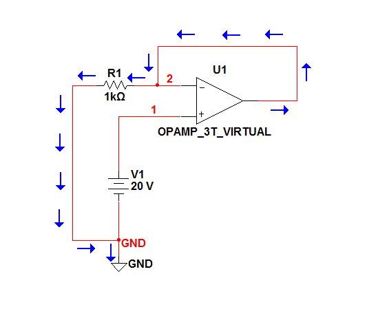
") In these circuits, it's all about Ohm's Law and statement I queried opposed the explanation we're to lead to. I queried for the benefit of the user asking the question and it's good for us all to stay away from bickering or insistences of being right despite the evidence. I'm glad that's the case here and we can just stick with the user's question in hand...
In these circuits, it's all about Ohm's Law and statement I queried opposed the explanation we're to lead to. I queried for the benefit of the user asking the question and it's good for us all to stay away from bickering or insistences of being right despite the evidence. I'm glad that's the case here and we can just stick with the user's question in hand...