Continue to Site

Welcome to EDAboard.com

Welcome to our site! EDAboard.com is an international Electronics Discussion Forum focused on EDA software, circuits, schematics, books, theory, papers, asic, pld, 8051, DSP, Network, RF, Analog Design, PCB, Service Manuals... and a whole lot more! To participate you need to register. Registration is free. Click here to register now.

Auto-Balancing Bridge for impedance masuremnet

Status
Not open for further replies.

Astrid

Full Member level 3
Joined
Jul 11, 2011
Messages
152
Helped
4
Reputation
8
Reaction score
3
Trophy points
1,298
Activity points
2,492
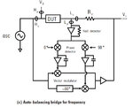
You advise as implemented, Auto balancing bridge to be in the LCR meter E4980A
Week thinking about how to implement the right of the oscillator, we advise?
We considered a DDS and a digital link (from Null detector), but I do not know how to implement the control amplitude with sufficient accuracy


ABB.jpg
 

I don't understand your particular problem related to amplitude control of the auto-balancing vector generator. Analog modulators as well as high resolution DACs can work for it, according to the general concept of your instrument. The respective Agilent patent application describes the function just as a mixer, see US2007024310. https://worldwide.espacenet.com/pub...locale=en_EP&CC=US&NR=2007024310A1&KC=A1&ND=4
 
  • Like
Reactions: Astrid

    Astrid

    Points: 2
    Helpful Answer Positive Rating
Thank you for the links, unfortunately, it works a little differently than we thought.
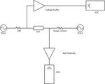
My idea was the LCR meter with a digitally controlled autobalanced bridge.
Description
Two DDS first as voltage source over DUT second as current source over current range resistor
Null detector measure voltage between DUT and range resistor and over procesor drive phase and amplitude second DDS
Phase driving no problem DDS have 14bit phase register (0,0219 Degre)
Amplitude control is problem for me. At 14bit DDS is ussable 13bit internal amplitude control (full amplitude - 1/2amplitude), but for resonable measuremt is need control over the entire range and high resolutio.
An idea?
DCABB.jpg
 
Last edited:

What's your intended ranging resistor granularity? It shouldn't be larger than 10:1. If 9 to 10 bit autobalancing amplitude resolution achievable with a 14 Bit DDS under this condition isn't enough, you can either use a higher resolution attenuator DAC behind the DDS generator, or measure the residual "null" voltage quantitatively and use it to interpolate between autobalancing steps.
 

What do you mean by "higher resolution attenuator DAC"?
Ranging resistor granularity? I'm still in the phase of reflection, but a maximum of 8 pieces (for example 10,100,1k,10k,100k,1M,..?, I would like to use CMOS analog switch, say ADG1414)
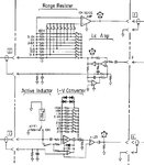
I looked at the implementation of the principle of LCR HP and I have several questions
see figure (D - Lcut BNC from DUT, C - Lpot BNC from DUT, G Output to modulator (second oscilator for balancingg bridge), F output form secnd oscilator, E output to vecrot ratio detector ,this is Err (voltage over range resitor)

1.Ichanel sense Amp (-input is Lcut BNC from DUT, output is Err to Vector ratio detector). I thing this is high speed instrumentation amplifier for measure voltage on range resistor, why? For control ,in case of unbalance bridge,...?
I do not understand, after all the whole complexity of balancing is to achieve maximum ZERO (virtual groud between DUT and range resistor? Voltage trom "second" oscilator is Err?

2.What is the function of LC Amp? -input from right is output of "balancing second oscilator"

3.I-V Converter. I thint this is Null Detector which converts difference betwen current over DUT and current over range resistor to voltage.
Why the amplifier gain -30? What is the function second amplieir below (imtegrator)? Completely escapes me is active coils.

Thank you
B2.jpg
 

What do you mean by "higher resolution attenuator DAC"?
A DAC with higher resolution, e.g 16-Bit, used as a programmable attenuator for the DDS output signal.
I looked at the implementation of the principle of LCR HP and I have several questions
From which document/instrument manual did you take the snippet?
 

I think I'm stupid :-D, how looks programmable atteunator with DAC ?
"All" my atteunator is PI with switching relay, sometime use something like **broken link removed**

This particular is from Agilent 4284A, but I thing all autobalancing <=2MHz LRC meter form HP use similar.
 

how looks programmable atteunator with DAC ?
A multiplying DAC with bipolar reference input can be used as attenuator. Achievable bandwidth is of course design depending.

I think all autobalancing <=2MHz LRC meter form HP use similar.
They are probably different regarding the implementation details you are asking for.

1. The Ich Sense Amp is providing the final current signal for the LCR measurement. In so far it's directly determining instrument accuracy.

2. LC amp and the respective auxilary amp in the I/V channel are there to sense/compensate the voltage at the cable screen.

3. Gain of -30, why at all an I/V converter? As every closed loop system, the auto balancing detector need to achieve stability (fulfill the Nyquist criterion). Loop gain matters.

3a. Active inductor. I'm with you, probably a kind of bias circuit for capacitive D.U.T.s.
 

A multiplying DAC with bipolar reference input can be used as attenuator. Achievable bandwidth is of course design depending.
do not know about a link to reference design?

Gain of -30. I thing, in real it is any as TIA.jpg
 

I even dared to question.
Figure from post #6
I looked at the section labeled LC Amp
I think (from rigth) inverting amplifier recieve signal for generating current over range resistor and at the same time over RC generating oposite current over shield of coaxial.
Buffer amplifeer on output inverting amplifier for one thing separate output for driving current over range resistor and second solve generating oposite DC current leaking over DUT when DC offset is used on DUT.
Unfortunately, I do not know what is the purpose and function lower amplifier (integrator)
A similar amplifier is also used in the lower parts I-V Converter.

You advise?
 
Nobody really know what is the purpose of the auxiliary amplifier (integrator or comparator) in Low current (LC Amp) and IV converer in Figure from the post 6.
To clarify talking about amplifiers with a capacitor in the feedback
 

Status
Not open for further replies.

Similar threads

Part and Inventory Search

Welcome to EDABoard.com

Sponsor

Back
Top