Continue to Site

Welcome to EDAboard.com

Welcome to our site! EDAboard.com is an international Electronics Discussion Forum focused on EDA software, circuits, schematics, books, theory, papers, asic, pld, 8051, DSP, Network, RF, Analog Design, PCB, Service Manuals... and a whole lot more! To participate you need to register. Registration is free. Click here to register now.

why and oscillator fix on specific value

Status
Not open for further replies.

baby_1

Advanced Member level 1
Joined
Dec 3, 2010
Messages
415
Helped
1
Reputation
2
Reaction score
1
Trophy points
1,298
Activity points
4,277
hello
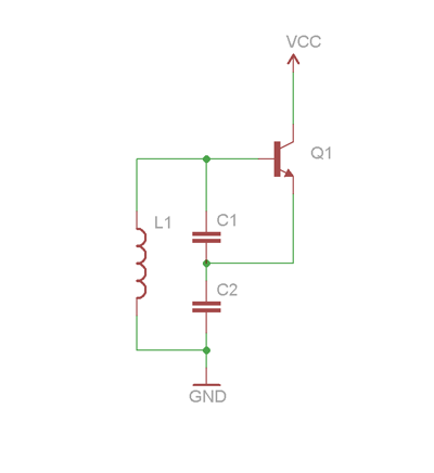
why and oscillator fix on specific value or how?
because the use positive feedback and the amplitude should increase and increase not fix how it fix?

example circuit
Colpitts.png
 

The oscillator is an amplifier with positive feedback. The amplitude increases until the amplifier reaches it's maximum output. Then it stops increasing because the amplifier can not give any greater output.

The circuit you show needs biasing before it can work.
 

Well....it is simple.... When you calculate the total loop gain(Amplifier gain* Feed back factor) of the circuit, it comes out ton be 1 and with a phase shift which is a multiple of 360 only for one frequency. This can be checked by writing down the transfer function for the feedback path and then equating the phase shift to 0 and the gain as inverse of amplifier gain... This is called Barkhausen principle.. For practical purposes though we make the loop gain slightly higher than 1 to prefer locking of the oscillator frequency.... Thus the oscillator fixes at one frequency and any change due to any reason is compensated with small vibrations in frequency and finally the frequency is again locked!
 

Thanks
as you know when the amplitude increase after some period time the output goes very high and transistor cutoff the amplitude.why it doesn't cutoff the output ?why it fix?
 

When the oscillator is powered, then the amplitude starts to increase. At this time the transistor provides pure sinewave signal to exite the LC. When amplitude reaches its limit then the transistor starts to switching (reapeted cutoff and saturation) or partially switching(reapeted cutoff and active). This type of switching will not degrade the shape of the sine wave,because LC is like a mass and spring(common differential equation). If you repeatedly(certainly at resonance frequency) hit any mass and spring combination you will see that they are making sinewave. When the amplitude further grows, then the cutoff time increases and saturation time decreases. As a result the LC will get less power to grow. If the amplitude still grows, then the saturation time will become so small that the LC will not get sufficient power to grow more. At that amplitude the LC will get stabilized.

---------- Post added at 02:57 ---------- Previous post was at 02:39 ----------

remember cutoff and saturation is happening at a rate of resonance frequency of the LC
 
  • Like
Reactions: baby_1

    baby_1

    Points: 2
    Helpful Answer Positive Rating
Hello
i can't understand why the loop gain feedback should higher than 1 so it doesn't infinite the fraction.
 

If it is higher than 1, the poles of the transfer function of the loop go into the right side of the imaginary axis. This will cause instability in the system if the poles stay there and do not oscillate back into the left side of the imaginary. When the amplification leads the poles to go to the right side, the circuit design we did pulls it back into the left thus establishing a dynamic equilibrium at unity
Note: It is a rule in electronic circuit design that the system becomes become unstable if its poles are on the right side of the imaginary axis, for reasons i cannot explain just by typing out. You can refer any book or material with rules for circuit design or transfer function rules and conditions.
 

When you have an LC tank loop (per schematic in OP), it will want to operate on a particular frequency. Nevertheless, the oscillator can stagnate unless the criteria discussed above are satisfied.

There must be the right give-and-take among several factors, in order for oscillations to sustain.
 

To summarize (and partly correct) some of the statements made before, I like to point out the following - applicable to each kind of harmonic oscillators (LC or RC):
* Each harmonic oscillator must be designed to enable the following condition (formulated in the 1930th by H. Barkhausen):
(1) Loop gain magnitude equal to unity for one single frequency only and (2) loop gain phase equal to zero (resp.360) deg.
This condition leads to a pure imaginary pole pair.

* Because this condition never can be met by a proper design (tolrances, drift,.) the loop gain magnitude is realized somewhat larger than unity. This condition leads to a pole pair within the right-hand part (RHP) of the s-plane. Thus, a secure start of oscillations is ensured. As a consequence, the amplitude at the ouput of the active device will continuosly rise until it is clipped (power rail of the active device).
* However, in case the frequency determining network is a high quality bandpass, the amplifier signal is filtered by the bandpass and a near-sinusoidal signal is available at the bandpass node (and a buffer is needed to decouple it from the load).
* In most cases a non-linear device (diodes, thermistor, FET-resistance) within the loop is added to prevent hard clipping and to limit the amplitude before it reaches the power rail value. In this case, a near-sinusoidal oscillator signal is available at the amplifier output node. This design leads to a pole pair that moves between the RHP and the LHP of the s-plane.
* I hope this answers some of the questions.
 
An oscillator is a non-linear device ( due to the non-linearity of the amplifier).Linearity implies, if f1, f2,f3 are given at the input of the device, then the output contains the same f1,f2,f3. When the circuit is powered up, the poles are located on the right half of the s-plane. This causes the output to grow exponentially. But, at some point, the gain of the amplifier saturates. This causes other frequecnies to be generated. But, as you would've noticed, most amplifiers have a frequency selective feedback network. This filters out the unwanted frequency components. So, only the frequency for which it is designed for is allowed and all other frequencies are not allowed to complete the loop. This causes the circuit to oscillate at that frequency. i.e. The poles move from the right half of the s-plane to the jw axis. Please refer this for images and other stuff. Any RF textbook will cover this in detail.

https://www.cppsim.com/CommCircuitLectures/lec11.pdf
 

............. But, as you would've noticed, most amplifiers have a frequency selective feedback network. This filters out the unwanted frequency components. So, only the frequency for which it is designed for is allowed and all other frequencies are not allowed to complete the loop. This causes the circuit to oscillate at that frequency. i.e. The poles move from the right half of the s-plane to the jw axis......

This description deserves some corrections. Unwanted frequency components cannot be "filtered out". They are only damped by the frequency selective network - if it is a lowpass or a bandpass! And only in case of a high-quality bandpass the filter action is sufficient to create a quasi-sinusoidal signal. For example, think of the classical WIEN oscillator. The bandpass in the feedback loop has a quality factor of 1/3. By far, this is not enough to "filter out" higher harmonics. There are even oscillators with a high pass in the feedback loop without any harmonics filtering.
Secondly, the nonlinearity does not move the poles to the jw axis. As mentioned before, the pole pair swings between the RHP and the LHP - as dictated by the laws of control theory.
 

Yeah, sorry, damped. FvM, please explain your last statement about how the poles swing between LHP and RHP.
 

Yeah, sorry, damped. FvM, please explain your last statement about how the poles swing between LHP and RHP.

OK, I will explain - but I am inclined to ask YOU to explain why you think the poles should "move from the right half of the s-plane to the jw axist". Exactly on the axis? This would be a surprise.

My explanation: The oscillation starts with a RHP pole pair and rising amplitudes. In order to stop rising the loop gain must be reduced automatically. Due to the delay in the circuit (remember: Each realistic loop has a delay) this reduction leads to a loop gain reduction below unity (with LHP poles) with a slight (for good design: a very slight) amplitude decrease. Then, the process starts again because the non-lineartity increases the loop gain again and shifts the poles to the RHP. This is a normal behaviour for each control loop which exhibits a kind of a small amplitude modulation.
 
  • Like
Reactions: baby_1

    baby_1

    Points: 2
    Helpful Answer Positive Rating
I agree with how the oscillation starts.

The amplifier is just a constant gain block being used (it saturates though, at high input signal amplitudes), and its a case of a frequency being allowed to complete the loop(with the necessary loop gain and phase shift) and others being damped. Please tell me where the poles go into the LHP in this case.

If at all the poles were to go to the left half plane, then the corresponding response in time domain is a decreasing exponential sine wave. So, the amplitude decreases and this in no way makes the amplifier or anything non-linear. Non-linearity occurs when amplitude increases and not when it decreases. Correct me if i'm wrong.
 
  • Like
Reactions: baby_1

    baby_1

    Points: 2
    Helpful Answer Positive Rating
The frequency of oscillator --
(2Pi)^(-1) * [ L(C1 + b*C2)]^(-1/2)
b is the parameter for such a transistor ie/ib!!
 
  • Like
Reactions: baby_1

    baby_1

    Points: 2
    Helpful Answer Positive Rating
The amplifier is just a constant gain block being used (it saturates though, at high input signal amplitudes), and its a case of a frequency being allowed to complete the loop(with the necessary loop gain and phase shift) and others being damped. Please tell me where the poles go into the LHP in this case.

OK, let me start with a "nice" sentence:
A "linear" (or harmonic) oscillator must contain a non-linear element. Only in this case it can operate in a quasi-linear way to deliver a near-sinusoidal signal. This sounds contradictory and indicates the problems connected with an exact analysis of oscillators behaviour.
My former explanations apply mostly to oscillators containing a "soft-limiting" non-linear extra device. Only in this case it is allowed to treat the oscillator as a quasi-linear circuit. Remember: All the rules and sentences about poles and transfer functions apply to linear systems only.
Exact analyses of oscillators containing "hard-limiting" amplifiers require non-linear differential equations.
However, there is a method to apply linear calculations also to hard-limiting non-linear devices (like saturated amplifiers).
This method is based on the harmonic balance principle using so called "describing functions".
But you have to know that this is an approximation only and that the classical method of pole location/distribution is not valid anymore. In this case, the Barkhausen condition (loop gain=1) is replaced by the condition
Hr(w)*A*B(a)=1.
Hr(w): Transfer function of the passive frequency-dependent network,
A: Constant gain amplifer,
B(a): Amplitude dependent describing function.
____________
I hope this helps to clarify things.
 
  • Like
Reactions: baby_1

    baby_1

    Points: 2
    Helpful Answer Positive Rating
Status
Not open for further replies.

Part and Inventory Search

Welcome to EDABoard.com

Sponsor

Back
Top