Continue to Site

Welcome to EDAboard.com

Welcome to our site! EDAboard.com is an international Electronics Discussion Forum focused on EDA software, circuits, schematics, books, theory, papers, asic, pld, 8051, DSP, Network, RF, Analog Design, PCB, Service Manuals... and a whole lot more! To participate you need to register. Registration is free. Click here to register now.

[SOLVED] Voltage divider to set diode current problem

Status
Not open for further replies.

Krebstar4000

Newbie level 3
Joined
Jun 12, 2010
Messages
3
Helped
0
Reputation
0
Reaction score
0
Trophy points
1,281
Activity points
1,309
I recently started reading Malvino Electronic Principles to further my understandings for hobby electronics. I've been stuck for a few hours on a problem out of chapter 3 of the 6th edition 3-29. "What value should R2 be to set up the diode current of 0.25 mA"
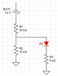
fig 3-21b.JPG

I'm not sure why I've been so stuck on this problem it seems easy enough on the surface. I know the answer is 23 k ohms but I can't get there.

The method that makes sense to me which doesn't give the correct answer is to calculate Vout needed by doing IR=V and that is .25mAx5kohm which gave me 1.25v for my Vout. from there I did R2 = R1/((Vin/Vout)-1) and that gives me 3.4k ohms which isn't the right answer.

I've gone around in circles but obviously I'm missing or misunderstanding a concept here and would like to be pointed in the right direction.

Thanks
 

Attachments

  • fig 3-21b.bmp
    428.5 KB · Views: 137

With 0.25mA through the diode, and therefore R3, the voltage across R3 is 1.25

The voltage at the junction of R1/R2 is then 1.25 plus the diode drop, say 0.6 = 1.85V

Across R1 will be 12 - 1.85 = 10.15V. The current through R1 is 10.75/30 = 1.015mA.

Of that, 0.25mA is in the diode plus R3 branch, so the remainder, 0.764mA, is through R2.

R2's value must be 1.85/0.765 = 2k418

Where did your 23k come from?

The 23k ohms was the answer given in the back of the book so I was attempting to follow the procedure to get an answer that matched. I can reasonably assume maybe there was an error in the answer given and it should be 2.3k that is close to the answer you gave you used 0.6v and the book consistently uses 0.7v drop across a diode so that could be the difference.

Is this how you would typically solve a problem like this? I'm not sure how practical this situation is or if it is a problem given as an exercise.

Thanks for the help
 

Krebstar4000,

The trick is to calculate the resistance of the diode at that current. Then current supplied by the voltage supply can then be calculated in terms of R2. Next we use the current division theorm and equate it to 0.25ma. The resistance of the diode is 0.7/0.25E-3 = 2800Ω. The total current supplied by the voltage source is 12/[30E3+R2||(5E3+2K8)] . Then we multiply the above term by R2/[R2+7K8] and equate it to 0.25E-3 . Solving for R2 gives 22941Ω which is close enough to the answer you want. So it involves two equations and two unknowns (I_total,R2).

Ratch
 
The method that makes sense to me which doesn't give the correct answer is to calculate Vout needed by doing IR=V and that is .25mAx5kohm which gave me 1.25v for my Vout. from there I did R2 = R1/((Vin/Vout)-1) and that gives me 3.4k ohms which isn't the right answer.

That would be the correct method, except that a different amount of current is going through R1 as through R2.

You calculated 3.4K. In fact that is the equivalent value for the two lower wires combined in parallel.

My simulator gives 23K as the correct value for R2.

R1 has 338 uA going through it.

R2 has 81 uA.

The diode wire has 257 uA.

The diode resistance is 2203 ohms.

Your figure of 1.25V across R3 is properly calculated.
 
the book consistently uses 0.7v drop across a diode so that could be the difference.
With only a quarter of a milliamp throught it, 0.6V is more realistic.

Is this how you would typically solve a problem like this?
Yes.

I'm not sure how practical this situation is or if it is a problem given as an exercise.
There may be practical situations which are similar, but I can't think of any right now! But it's a useful excercise nevertheless.
 
BradtheRad,

You calculated 3.4K. In fact that is the equivalent value for the two lower wires combined in parallel.

I calculated 7800||22941 = 5820Ω

My simulator gives 23K as the correct value for R2.

Yes, that is correct.

The diode wire has 257 uA.

No, the diode has 250 µa by problem definition.

The diode resistance is 2203 ohms.

No, the diode resistance is 0.7/0.25E-3 = 2800Ω

Your figure of 1.25V across R3 is properly calculated.

Yes, that is correct.

Syncopator,

Across R1 will be 12 - 1.85 = 10.15V. The current through R1 is 10.75/30 = 1.015mA.

The current through R1 will be 10.15/30K = 338µa.

Ratch
 
Thanks everyone for the assistance this did in fact point me in the correct direction to help solve problems similar to this in the future.
 

Status
Not open for further replies.

Part and Inventory Search

Welcome to EDABoard.com

Sponsor

Back
Top