Continue to Site

Welcome to EDAboard.com

Welcome to our site! EDAboard.com is an international Electronics Discussion Forum focused on EDA software, circuits, schematics, books, theory, papers, asic, pld, 8051, DSP, Network, RF, Analog Design, PCB, Service Manuals... and a whole lot more! To participate you need to register. Registration is free. Click here to register now.

is it possible in cadence trans analysis

Status
Not open for further replies.

muffassir

Member level 3
Joined
Sep 15, 2011
Messages
67
Helped
10
Reputation
20
Reaction score
10
Trophy points
1,288
Location
Planet Earth
Activity points
1,802
Hi All,

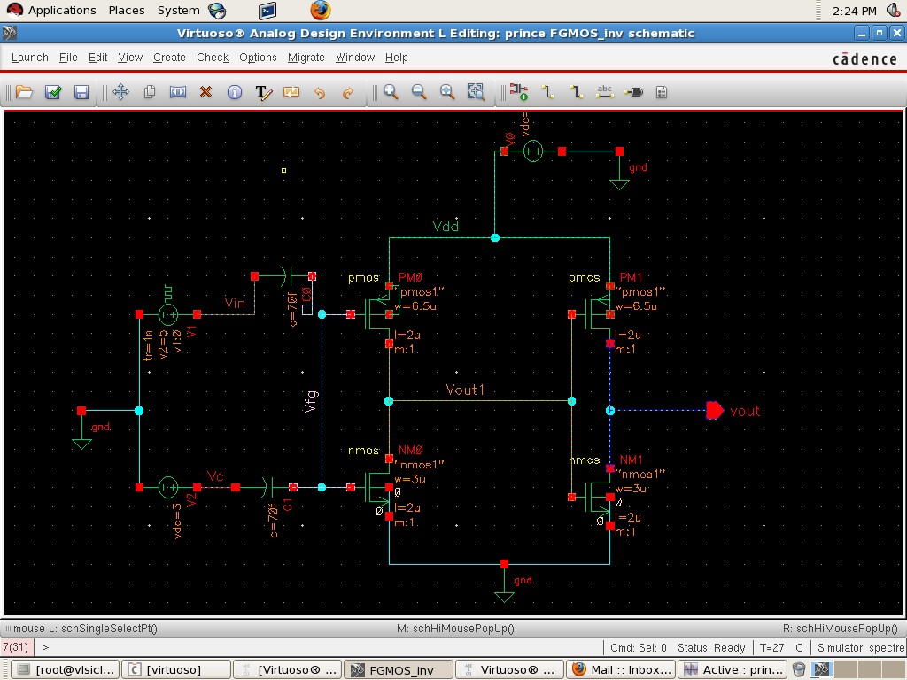
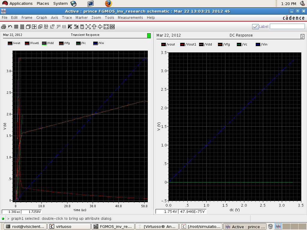
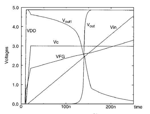
I came across this particular waveform of the Transient analysis see attached image..

32_1332231119.jpg


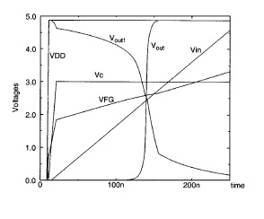
DO you all think is it possible to get such waveforms using trans analysis.
What could be the Vin .Is it a square vpulse or traingular vpulse?


Thanks in advance

Muffassir
 

Yes it should be easy to do. Vin could be a triangle or pulse. I usually just use a pulse with slow rise time to get a triangle or sawtooth.

Keith
 

How to do the trans analysis of this ckt?

Hi all,


I want to do the simulation of this circuit from IEEE paper.I have redrawn it in cadence.


I am expecting such kind of waveforms after the simulation(attached image is screeenshot of pdf)


For doing the simulation the author says .......


I have done the simulation by taking help from one of the previous threads here on edaboard.
I selected skipdc=yes in trans analysis,use the writefinal option in Transient analysis and read
that file using readns in DC-Analysis options.

<<<<BUT the above didnot helped me...From the authors quote as above in image can anyone please suggest me the selection of options in trans and dc forms or something else>>>


Thanks in advance


Muffassir
 
I have merged the threads. Don't start new threads asking the same question.

Keith.

---------- Post added at 09:55 ---------- Previous post was at 09:52 ----------

You don't want to skip the DC bias point calculation. You should simply start with the power supplies and other inputs at zero and create a fast ramp for Vdd. That is described in the clip you posted.

Keith.
 
You should simply start with the power supplies and other inputs at zero and create a fast ramp for Vdd. That is described in the clip you posted.

Should the Vdd be vpulse with the pulsewidth=0 ;
And how can i set the power supplies Vin and Vc inputs=0. Will you please elaborate on this ..I dont know how to do this.I am new to cadence.

Thanks.
 
No, VDD needs to be a pulse with a very long pulse width - as long as your transient anlaysis. Also, add a small start delay so the voltage is zero for a short time before it starts to rise. Something like

V1 VDD 0 Pulse(0 3.3 200n 1u 1u 100u)

would give a 3.3V pulse 100us long with 200ns delay and 1us rise/fall time.

For Vin/Vc you do the same thing - instead of using a DC voltage use a pulse.

Keith.
 
Thanks Keith,


I simulated the circuit using Vdd as vpulse(V1=0,V2=3.3, Period=120us, Delay=200ns, tr=tf=1u, Pulsewidth=75us)

Vin as triangular wave ( V1=0,V2=3.3, Period=100us, Delay=200ns, tr=tf=50us, Pulsewidth=0)

Vc as Pulse( V1=0,V2=2V, Period=100us, Delay=500ns, tr=tf=2u, Pulsewidth=50us)

for setting the power supplies.

W/L of both inverters are PMOS=6.5u/2u and NMOS=3u/2u.

The outputs i am getting after the simulation are shown in the image outinverter.png and expected outputs from IEEE paper are shown in the outexpected.png.


The outputs for Vout1 and vout are not according to the exxpected. Also i am not able to get the DC transfer characteristics of the above circuit.I have even also set readns=spectre.fc file from trans analysis.

On the basis of the statement by the author is there any thing i can set the options in trans/dc options so that i can get the output of DC characteristics/trans analysis.

Any help is much appreciated.


Thanks
 

I suspect the differences are due to the process and voltages, but I cannot be sure. You are only using 3V rather than 5V - I guess it is a smaller geometry process than the original paper. However, your transistor lengths are quite high for a small geometry. I think the problem may be a design one rather than due to simulation. Also, reduce the transient analysis maximum step size. It isn't a problem at the moment but the defaults are usually too high.

Keith.
 
Hi Keith,

Thanks a lot for the help .I got the expected waveforms.The only thing i did is ...
In the capacitors properties there is an field for Initial condition i set it to '0' .
That did the job !!!

Regards,

Muffassir
 

Status
Not open for further replies.

Part and Inventory Search

Welcome to EDABoard.com

Sponsor

Back
Top