Continue to Site

Welcome to EDAboard.com

Welcome to our site! EDAboard.com is an international Electronics Discussion Forum focused on EDA software, circuits, schematics, books, theory, papers, asic, pld, 8051, DSP, Network, RF, Analog Design, PCB, Service Manuals... and a whole lot more! To participate you need to register. Registration is free. Click here to register now.

60 Hz sine wave to TTL clock signal (pulse shaping help)

Status
Not open for further replies.

kpax

Newbie level 3
Joined
Mar 3, 2012
Messages
3
Helped
0
Reputation
0
Reaction score
0
Trophy points
1,281
Location
Canada
Activity points
1,314
I am designing a simple circuit that will take a 12 V 60 Hz AC sine wave and turn it into a 60 Hz clock signal for a TTL clock. I have Schmitt trigger inverters or buffers to use. I am unsure on how to interface the sine wave signal to the Schmitt trigger. I am thinking that I need to rectify the voltage, and then create a basic voltage divider circuit to get a half-wave positive only signal with a 5 V peak voltage. Is this the simplest way to do this? Is there an easier way? Timing is important, but it doesn't need to be a perfect square wave, just as long as the frequency is 60 Hz.
 

You can use op-amp as comparator for your task.To get a TTL O/P provide op-amp with +5V and GND.
Below is the schematic of the circuit.I have used a voltage divider to reduce 12V to 3V as supply is only 5V.


Hope this solves your problem!!
 
  • Like
Reactions: iVenky

    iVenky

    Points: 2
    Helpful Answer Positive Rating
Dear kpax
Hi
I think you are at the wrong way . can you tell me a bit more explanation , that what do you want to do , clearly , thus i can help you .
Regards
Goldsmith
 

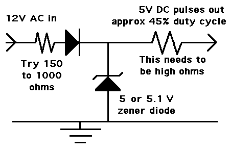
Rectify with a diode, drive an NPN transistor through a resistor with Emitter to ground. 5v through a resistor to collector, where you´ll have a 60 Hz. square wave. Sorry, I can only draw with EAGLE and it´s not allowed. Very big shame.
 

This is a cheap and easy way. It is only suitable if you can get by with less than 50 % duty cycle.

The transitions will be slightly inclined. You can always run it through a comparator or schmitt trigger if you need vertical transitions.

93_1331013554.gif
 

    V

    Points: 2
    Helpful Answer Positive Rating
You can use op-amp as comparator for your task.To get a TTL O/P provide op-amp with +5V and GND.
Below is the schematic of the circuit.I have used a voltage divider to reduce 12V to 3V as supply is only 5V.


Hope this solves your problem!!

Why did you includes some resistors in the beginning? Can't we just give the sinusoidal wave to the positive terminal?

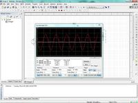
Also it would be really useful if you plot the waveform and upload it.
 

Here is the output waveform for the circuit i have put.
 

Or,


Vin = 12VRMS (17.98V P-P) 60HZ
 

Would a half wave voltage recitifier and voltage divider work, using a diode and two resistors? The output is fed into a schmitt trigger. it doesn't need to be 50 percent duty cycle. I am using it as a 60 Hz clock signal (ie vertical transitions).
 

Would a half wave voltage recitifier and voltage divider work, using a diode and two resistors? The output is fed into a schmitt trigger. it doesn't need to be 50 percent duty cycle. I am using it as a 60 Hz clock signal (ie vertical transitions).

Yes, you can do this. With care.

Keep in mind the tricky situation when you let either AC line, carrying first 17 V positive, then 17 V negative volt levels, come into contact with devices meant for much lower volt levels.

You'll use one of the AC wires as a zero reference. But you must ensure there is no hazardous current path through your other devices.

Also you must limit the peaks so as not to exceed tolerable limits for whatever device you feed it to (schmitt trigger as you say). Neither the upper positive limit or the negative-going limit.
 

Come on kpax; RJM´s cicuit works fine. I know because I have one working for years! although I rectified first. If you need more protection just use an optoisolator circuit.
 

Advisable to use a back to back parallel set of diodes instead of the 1Kohm resistor to ground.The output shall be clean square wave with sharp transitions at the zerocrossing.The schmidt trigger shall find exact 60Hz transitions Hi and low for timimg of the TTL data.
 

Status
Not open for further replies.

Part and Inventory Search

Welcome to EDABoard.com

Sponsor

Back
Top