Continue to Site

Welcome to EDAboard.com

Welcome to our site! EDAboard.com is an international Electronics Discussion Forum focused on EDA software, circuits, schematics, books, theory, papers, asic, pld, 8051, DSP, Network, RF, Analog Design, PCB, Service Manuals... and a whole lot more! To participate you need to register. Registration is free. Click here to register now.

[SOLVED] Zero cross detection for 220VAC with PIC18F452

Status
Not open for further replies.

losturcos

Member level 4
Joined
Aug 30, 2007
Messages
76
Helped
4
Reputation
8
Reaction score
3
Trophy points
1,288
Activity points
1,838
Hello,
I am trying to sense zero cross for 220VAC with PIC microcontroller, PIC18F452. I have read AN521 microchip application note which gives the theory for sensing the zero cross with only one resistor. In the app note the example controller is PIC16C5X which has input protection diodes internally.
My question is, do these diodes exist in 18F452? I couldnt see it at the datasheet.
I have prepared a small circuit in Proteus. I couldnt get a result. I only connected a sinus 220VAC / 50 Hz to porta.1, and tried to sense it.
Have I misunderstood something.
Thanks.
 

Re: Zero Cross Detection

The protection diodes are on all PICs (in fact, on almost all ICs).

Keith
 
Re: Zero Cross Detection

Thanks for quick reply. What can be my mistake? I am testing with an "if" in "while(1)" loop to see at any time it passes to zero.
 

Re: Zero Cross Detection

Misconfiguration of the port pins? Software bug? Is your sine wave centred around 0V? Is it something Proteus can simulate correctly?

Without more information we can only guess.

Keith
 
Re: Zero Cross Detection

I dont think a misconfiguration exist. Should I configure the input as analog input? Anyway, I have tried both.

Code:
while(1)
{
	if(inputR)
		outputR = 1;
	else
		outputR = 0;
}
This is what all I do, to see if it senses. TRIS registers are configured.
Note: inputR and outputR are configured port pins.
 

Re: Zero Cross Detection

I dont think a misconfiguration exist. Should I configure the input as analog input? Anyway, I have tried both.
...
...
...
TRIS registers are configured.

I would suggest you post your ENTIRE program, rather than the small snippet.

It often requires more than just properly configuring the TRIS registers. Depending on the PORT and the PIN in use, you may have to disable ADC, Comparator Modules, etc.

Reference: PIC18FXX2 Datasheet, Section: 9.1 PORTA, TRISA and LATA Registers, Pg. 87

The other PORTA pins are multiplexed with analog
inputs and the analog VREF+ and VREF- inputs. The
operation of each pin is selected by clearing/setting the
control bits in the ADCON1 register (A/D Control
Register1).


Note: On a Power-on Reset, RA5 and RA3:RA0
are configured as analog inputs and read
as ‘0’. RA6 and RA4 are configured as
digital inputs.

It may very well be a "misconfiguration" issue, however unless you post your entire code, we'll never know.

BigDog
 
Re: Zero Cross Detection

The program is as below, it is written in CCS C.

Code:
#include <18F452.h>
#include <PIC18F452_registers.h>
#fuses HS, NOWDT, PROTECT, NOLVP, /*BORV42*/ NOBROWNOUT, PUT
#define ANALOG_PINS 	AN0
#device HIGH_INTS = TRUE
#device   ADC = 10                                       //
#use delay(clock=20000000, restart_wdt)               //

#BIT  inputR = PORTB.6
#BIT  outputR = PORTB.0

main()
{
	port_b_pullups(false);								//

	setup_adc_ports(ANALOG_PINS);
	setup_adc(ADC_CLOCK_DIV_32);
	set_adc_channel( 2 );

	// setup_lcd(LCD_DISABLED);

	TRISA = 0b11111111;									//
   TRISB = 0b11111000;									//
	TRISC = 0b00000000;									//
	TRISD = 0b00000000;									//
	TRISE = 0b00000000;									//

	PORTC = 0;
	PORTB = 0;   											//
	PORTA = 0;
	PORTD = 0;

	while(1)
	{

		if(inputR)
		{
			outputR = 1;
		}
		else
		{
			outputR = 0;
		}
	}
}
 

Re: Zero Cross Detection

By the way, I had changed the input port as portb.6 different from the beginning.
 

Re: Zero Cross Detection

PORTB.6 is a programming pin. Please check that your programmer is not connected during your tests!

And I suggest to use the following define: #BIT outputR = LATB.0
 
Re: Zero Cross Detection

I have tried other pins, too. Also I have tried as #BIT inputR = LATB.6 or LATB.4, too.
And I am making the tests in proteus, so there is no programmer device.
I have set an "On change" condition for PORTB in the simulation, that doesnt change, too.
What can be the problem?
 

Re: Zero Cross Detection

How you are generating AC input sequence on your schematic?
Could you share schematic you are using? Or check the signal on your input pin using oscilloscope window.
 
Re: Zero Cross Detection

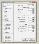
The sine generator and the circuit is as below. I have set the frequency as 10 Hz. to make easier to see the wave.

SineGenerator.jpg
circuit.jpg
 

Re: Zero Cross Detection

Yes, you are right. Thank you very much.
 

Status
Not open for further replies.

Part and Inventory Search

Welcome to EDABoard.com

Sponsor

Back
Top