Continue to Site

Welcome to EDAboard.com

Welcome to our site! EDAboard.com is an international Electronics Discussion Forum focused on EDA software, circuits, schematics, books, theory, papers, asic, pld, 8051, DSP, Network, RF, Analog Design, PCB, Service Manuals... and a whole lot more! To participate you need to register. Registration is free. Click here to register now.

Providing common mode voltage to instrumentation amp

Status
Not open for further replies.

PeterTr

Newbie level 6
Joined
Feb 7, 2012
Messages
11
Helped
0
Reputation
0
Reaction score
0
Trophy points
1,281
Activity points
1,376
Hello,

I am asking advice on how to properly provide a common mode (CM) voltage to an instrumentation amp.
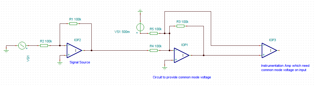
Attached you find a circuit I came up with and I am asking if there is a better/simpler way to provide the CM.
The relevant part of the circuit is the one labeled "Circuit to provide common mode voltage".

Thank you!
Peter


strange circuit ... the first stage (IOP2) is already referred to GND, so you don't need an instrumentation amplifier at all!
 

Thanks for the reply.
Actually the inamp is part of an ADC (AD7793). From the datasheet it says that the common mode is required to operate the device properly. I was hoping that the provided circuit would make it easier to explain the problem ...

Still any advice ?

Regards
Peter
 

The schematic seems rather to confuse the original problem then clarifying anything. At least, it doesn't manage to generate a positive common mode voltage. As drawn, the negative ADC input is connected to zero (virtual ground) and a negative offset given to the positive input.

The supply voltage of the OPs isn't shown, so it's unclear if they are able to generate a negative output voltage.
 

Your ADC has a single supply - call it VCC.
If your input source is bipolar, you want to connect the AIN- of the ADC to VCC/2: this maximize the input range.
So you can build VCC/2 (a resistor voltage divider may be enough), connect EVERYTHING to VCC/2 and remove IOP1 (everything means: return of VG1, non-inverting inputs of IOP2 and IOP3).

Otherwise, if your OPAMPs have a simmetrical supply (+/- something), Vs1 must be negative.
 

    V

    Points: 2
    Helpful Answer Positive Rating
to FvM:
I have to admit that my circuit drawing was rather confusing than helping to explain the problem. I guess it saves everybody's time the phrase the questions in much detail. Lesson learned !

to dave9000:
Thanks for your reply! In my spice simulation your suggestion worked as expected. The opamps have a symmetrical supply, by the way ...
My only problem now is that my existing circuit for the input source is referenced to GND. From your explanation I assume that I need to reference the complete analog input circuit to Vcc/2. My question is, if it is possible to generate the reference to Vcc/2 only for the final stage of the circuit, which in my case is a Sallen-Key lowpass filter.
Thanks again!
Peter
 

You can perform the necessary level shift anywhere in the signal chain, taking care that no noise or drift are added to the signal.

Do I understand right, that bipolar OP supplies are generally available, only the ADC is restricted to unipolar operation (by design)?

In this case a differential amplifier would be preferred to achieve correct translation of signal ground to ADC input reference. It may be also suggested to generate a symmetrical differential signal, e.g. to improve ADC linearity, at least this is the case for wide band signals.
 

    V

    Points: 2
    Helpful Answer Positive Rating
to FvM:
Thanks for the reply! Your assumption about the bipolar OP supplies is correct. I appreciate your reference to to the usage of a differential amplifier. I was reading up on it in the AD8476 datasheet. Learning is fun !
I will first give the simple level shifting with Vcc/2 a try before resorting to more advanced techniques.
Best regards
Peter
 

Status
Not open for further replies.

Similar threads

Part and Inventory Search

Welcome to EDABoard.com

Sponsor

Back
Top