folarinv
Newbie level 1
pic16f628 circuit
I tried to build an inverter using PIC16F628A (circuit diagram and codes are attached) but the problems is that the highest voltage I recorded on the output was 110Vac instead of 220Vac. Could there be something I've not done rightly or a better way of making an inverter (12Vdc/220Vac).
best regards
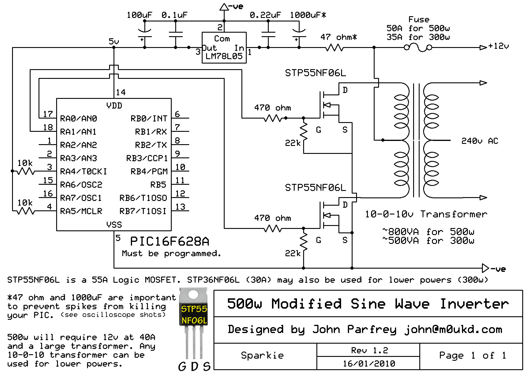
") so can you attach better shematic and code (HEX file) for inverter with some pic DC/AC inverter 12/220V 50Hz 500W with protection(low batery pr. overload pro short circuit )..Have you build any Sine wave inverter..!? please attach files if you have..Thanks.. and sorry for my bad english
so can you attach better shematic and code (HEX file) for inverter with some pic DC/AC inverter 12/220V 50Hz 500W with protection(low batery pr. overload pro short circuit )..Have you build any Sine wave inverter..!? please attach files if you have..Thanks.. and sorry for my bad english