Lot of people who start with HFSS have issues in making the complicated geometry in HFSS. Here are very simple steps which anyone can follow to make a 3D structure in HFSS

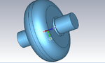
Just take example of this cavity with attached beam pipes
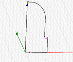
Step 1 Draw this 3D structure on paper as 2D line Diagram which will look like this

Have a closer look it is 1/4th of 2D Line Diagram of total cavity
This is what you have to actually draw in HFSS then just using some very simple commands in HFSS you can convert it into 3D cavity.
Step 2 Draw the line diagram starting from any corner of 2D Line Diagram with following commands of HFSS
For first line
Draw>Line

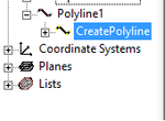
It will appear in History tree
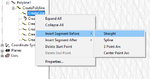
For all other lines

This is very important step as not to use the Draw>Line command again
You can add lines of your choice from the options available in HFSS
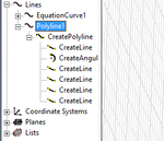
When finished it should look like this

Have a careful look we have only one poly line tree defining all the lines
Now you have finished drawing 2D Line model
You can use relative coordinate system to draw lines with more ease
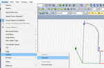
Step 3 converting line model to sheet
Select all lines to this hold Ctrl key and click the line
then use Modeler>Surface> connect command as shown below

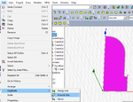
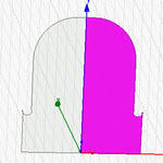
Step 4 converting 1/4 2D slice to 1/2 2D slice
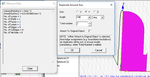
Edit>Duplicate>Around Axis command as shown below

Enter the Axis around which you want to duplicate which is Y here and angle 180 as shown below

Once it is done it will look like this

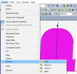
Step 5 Adding the two slices
select the two slices in history tree then Modeller>Boolean>unite as shown below

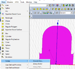
Step 6 Converting 2D geometry to 3D geometry
Use Draw>Sweep>Around Axis as shown below

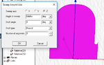
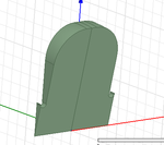
Enter the axis around which it should swept which is Z in this case and angle to be swept 360 means complete cavity you can enter variable as $alpha in this case to have flexible 3D slice as shown below

You are done you have flexible 3D geometry slice controlled by $alpha angle 10 degree slice will look like this

Now you can assign materials, boundaries excitations and proceed with your simulation
Just take example of this cavity with attached beam pipes
Step 1 Draw this 3D structure on paper as 2D line Diagram which will look like this
Have a closer look it is 1/4th of 2D Line Diagram of total cavity
This is what you have to actually draw in HFSS then just using some very simple commands in HFSS you can convert it into 3D cavity.
Step 2 Draw the line diagram starting from any corner of 2D Line Diagram with following commands of HFSS
For first line
Draw>Line
It will appear in History tree
For all other lines
This is very important step as not to use the Draw>Line command again
You can add lines of your choice from the options available in HFSS
When finished it should look like this
Have a careful look we have only one poly line tree defining all the lines
Now you have finished drawing 2D Line model
You can use relative coordinate system to draw lines with more ease
Step 3 converting line model to sheet
Select all lines to this hold Ctrl key and click the line
then use Modeler>Surface> connect command as shown below
Step 4 converting 1/4 2D slice to 1/2 2D slice
Edit>Duplicate>Around Axis command as shown below
Enter the Axis around which you want to duplicate which is Y here and angle 180 as shown below
Once it is done it will look like this
Step 5 Adding the two slices
select the two slices in history tree then Modeller>Boolean>unite as shown below
Step 6 Converting 2D geometry to 3D geometry
Use Draw>Sweep>Around Axis as shown below
Enter the axis around which it should swept which is Z in this case and angle to be swept 360 means complete cavity you can enter variable as $alpha in this case to have flexible 3D slice as shown below
You are done you have flexible 3D geometry slice controlled by $alpha angle 10 degree slice will look like this
Now you can assign materials, boundaries excitations and proceed with your simulation