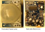
In this project a Passive Infrared (PIR) sensor is used to detect human movement and trigger an alarm. A typical PIR sensor comes pre-packaged with all the logic required to, detect IR radiation from living being and raise alarm. Similar PIR modules have just three pins, two for power supply (up to 12volt) and third for output. So, all that is required to do is to connect it to the power supply and connect the out pin to a microcontroller pin to detect any changes (detect high or low).

I have seen many projects in the net where the PIR output pins are directly connected to microcontroller pins. But such arrangement did not work in my case.
I have purchased the PIR module from a shop of Chandni Market, Kolkata (Biggest electronics component market in eastern part of India). The market is notorious for parallel gray market sale. Some of the shops sell components without any papers even cash memo at a very low price. My PIR module costs INR Rs. 350/- without any papers. There was no manufacturer name written anywhere.
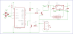
At first I had my PIR module’s output connected directly to a pin of pic16F84A microcontroller and did not get proper result. My microcontroller was sensing only high output from the PIR module on all conditions. So I checked the output of the PIR module and found that when connected to a 5 volt supply, the output pin voltage was about 2.66 volts and after detecting a movement the output pin voltage was about 3.44 volts! According to the datasheet of pic16F84A, input low voltage should be 0.2VDD. So I have used a BC547B with the PIR output as a switch to provide proper logic levels to the microcontroller.
[Comments from the reader are appreciated if they have faced a similar situation.]
I have used a pic16F84A microcontroller with 4MHz crystal and MikroC Pro Compiler.
To know more on how PIR module works see: How to use Pyroelectric ("Passive") Infrared Sensors (PIR)
Testing your PIR
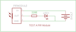
It is a good idea to go through a simple test to verify that it works the way you expect. This test is also good for range testing. Simply connect the + pin of the PIR to the positive rail of a good power supply (3.5VDC to 6V) and connect ground to the - pin on your PIR. Then connect an LED (commonly available 2mA current and about 2 volt forward voltage drop) and a 220Ω resistor to the out pin as shown.

Wait for 1 minute. Now when the PIR detects motion, the output pin will go "high" to 3.4V and light up the LED! [Check the voltage]. After that, stand still. After a few seconds the output line will drop to 2.66 volt. You can check this low voltage when the PIR module is facing opposite side. Otherwise a slight movement will make the output go up again.
Range is about 16f
Codes:-
//Alarm using PIR module.
//PIC16F84A microcontroller using 4MHz Crystal
// A buzzer is used as a sound producer
sbit pir_in at RA0_bit; //PIR module's output pin
sbit led_ind at RA1_bit; //An LED used as indicator
sbit buz_out at RB4_bit; //Buzzer output
sbit pir_in_Direction at TRISA0_bit;
sbit led_ind_Direction at TRISA1_bit;
sbit buz_out_Direction at TRISB4_bit;
void init_delay(); //initial delay routine's forword declaration
int i; //declare for using with for loops both in main and
//in the delay routine
void main() {
pir_in_Direction=1; //as input
led_ind_Direction=0; //as output
buz_out_Direction=0; //as output
led_ind=0; //initially off
buz_out=0; //initially off
init_delay(); //1 min delay to activate the PIR module
while(1){
while(pir_in==0){
buz_out=1;
for( i=0;i<15;i++){ //Buzzer sounds for 15 seconds
led_ind=0;
Delay_ms(500);
led_ind=1;
Delay_ms(500);
}
buz_out=0;
led_ind=0;
}
}
}
void init_delay(){
for(i=0;i<30;i++)
{
led_ind=1;
Delay_ms(500);
led_ind=0;
Delay_ms(500);
}
led_ind=0;
}
//////////////////////////////////////////////////////////////////////
Circuit diagram:-

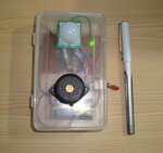
Finished Project

I have seen many projects in the net where the PIR output pins are directly connected to microcontroller pins. But such arrangement did not work in my case.
I have purchased the PIR module from a shop of Chandni Market, Kolkata (Biggest electronics component market in eastern part of India). The market is notorious for parallel gray market sale. Some of the shops sell components without any papers even cash memo at a very low price. My PIR module costs INR Rs. 350/- without any papers. There was no manufacturer name written anywhere.
At first I had my PIR module’s output connected directly to a pin of pic16F84A microcontroller and did not get proper result. My microcontroller was sensing only high output from the PIR module on all conditions. So I checked the output of the PIR module and found that when connected to a 5 volt supply, the output pin voltage was about 2.66 volts and after detecting a movement the output pin voltage was about 3.44 volts! According to the datasheet of pic16F84A, input low voltage should be 0.2VDD. So I have used a BC547B with the PIR output as a switch to provide proper logic levels to the microcontroller.
[Comments from the reader are appreciated if they have faced a similar situation.]
I have used a pic16F84A microcontroller with 4MHz crystal and MikroC Pro Compiler.
To know more on how PIR module works see: How to use Pyroelectric ("Passive") Infrared Sensors (PIR)
Testing your PIR
It is a good idea to go through a simple test to verify that it works the way you expect. This test is also good for range testing. Simply connect the + pin of the PIR to the positive rail of a good power supply (3.5VDC to 6V) and connect ground to the - pin on your PIR. Then connect an LED (commonly available 2mA current and about 2 volt forward voltage drop) and a 220Ω resistor to the out pin as shown.
Wait for 1 minute. Now when the PIR detects motion, the output pin will go "high" to 3.4V and light up the LED! [Check the voltage]. After that, stand still. After a few seconds the output line will drop to 2.66 volt. You can check this low voltage when the PIR module is facing opposite side. Otherwise a slight movement will make the output go up again.
Range is about 16f
Codes:-
//Alarm using PIR module.
//PIC16F84A microcontroller using 4MHz Crystal
// A buzzer is used as a sound producer
sbit pir_in at RA0_bit; //PIR module's output pin
sbit led_ind at RA1_bit; //An LED used as indicator
sbit buz_out at RB4_bit; //Buzzer output
sbit pir_in_Direction at TRISA0_bit;
sbit led_ind_Direction at TRISA1_bit;
sbit buz_out_Direction at TRISB4_bit;
void init_delay(); //initial delay routine's forword declaration
int i; //declare for using with for loops both in main and
//in the delay routine
void main() {
pir_in_Direction=1; //as input
led_ind_Direction=0; //as output
buz_out_Direction=0; //as output
led_ind=0; //initially off
buz_out=0; //initially off
init_delay(); //1 min delay to activate the PIR module
while(1){
while(pir_in==0){
buz_out=1;
for( i=0;i<15;i++){ //Buzzer sounds for 15 seconds
led_ind=0;
Delay_ms(500);
led_ind=1;
Delay_ms(500);
}
buz_out=0;
led_ind=0;
}
}
}
void init_delay(){
for(i=0;i<30;i++)
{
led_ind=1;
Delay_ms(500);
led_ind=0;
Delay_ms(500);
}
led_ind=0;
}
//////////////////////////////////////////////////////////////////////
Circuit diagram:-
Finished Project